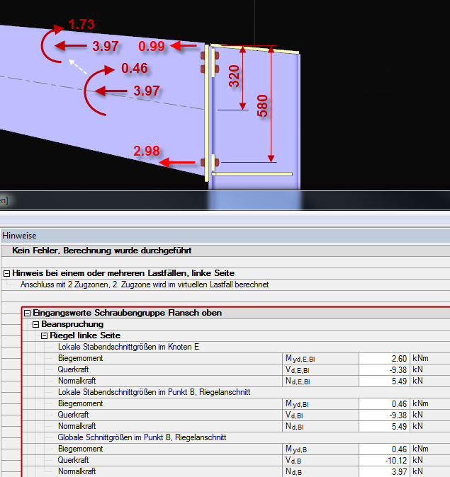
In several individual design checks (for example, column flange under bending), the applied bending moments are related to a compression point. The eccentricity of the axial force is converted into an additional moment. In the case of predominant tensile forces, the compression component due to the moment is superimposed so strongly that the second tension zone is created instead of the compression point (see image).
Question
What is the meaning of the calculation message "Connection with 2 tension zones, 2nd tension zone will be calculated in virtual load case"?
Use the "Independent mesh preferred" option in the FE mesh settings to create an independent FE mesh for the integrated objects. This allows you to generate a significantly more detailed and precise FE mesh for individual objects that are integrated into one another.
In the "Edit Section" dialog box, you can display the buckling shapes of the Finite Strip Method (FSM) as a 3D graphic.
In RFEM 6 and RSTAB 9, you have the option to enter "Visual Objects" as guide objects. You can import the file formats 3ds, stl, and obj.
These objects allow you to create a better reference to the dimensions.
Do you have individual column sections and angled wall geometries, and need punching shear design for them?
No problem. In RFEM 6, you can perform punching shear design not only for rectangular and circular sections, but for any cross-section shape.