FAQ 004955 EN-US
New
02/24/2021
004955
How can I perform the stability analysis in RF‑/STEEL EC3 for a flat bar supported on edges, such as 100/5? Although the cross-section is rotated by 90° in RFEM/RSTAB, it is displayed as lying flat in RF‑/STEEL EC3.
Answer
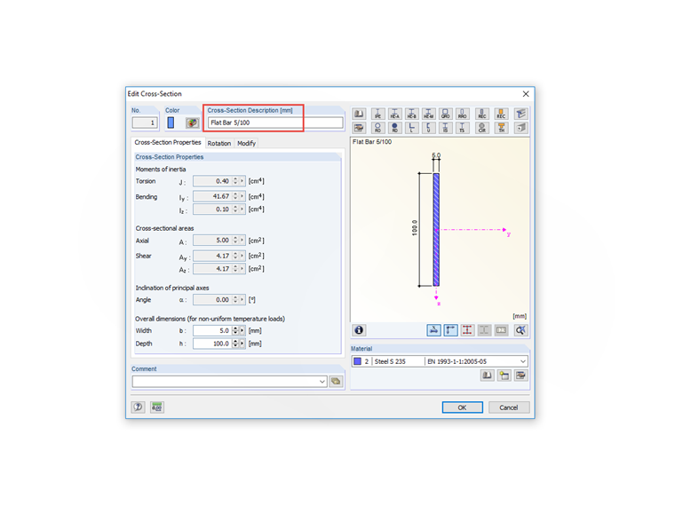
In RF‑/STEEL EC3, the uniaxial bending stress is always related to the local y-axis of a member and the local y-axis of a member is always assumed as the major axis in the case of symmetric cross-sections, therefore it is only possible in such a case to change the cross-section description from "100/5" to "5/100", see the image. Thus, the stability analysis is performed accordingly.
Keywords
Flat bar Stability Buckling Edgewise
Downloads
Contact us
Did you find your question?
If not, contact us via our free e-mail, chat, or forum support, or send us your question via the online form.
Recommended Events
Eurocode 3 | Steel structures according to DIN EN 1993-1-1
Online Training 05/06/2021 8:30 AM - 12:30 PM CEST
Designing Cold-Formed Steel Sections According to Eurocode 3
Webinar 04/30/2020 3:00 PM - 3:45 PM CEST
Membrane Structures with Wind Loads from CFD Wind Simulation
Webinar 03/24/2020 3:00 PM - 4:15 PM CET
Dlubal Webinar: Design of Steel Structures According to EC 3 | Part 2: Stability Analysis, Design
Webinar 12/01/2017
Dlubal Webinar: Design of Steel Structures According to EC 3 | Part 1: Modeling, Loading
Webinar 11/24/2017 3:00 PM - 4:00 PM CET
Videos
KB 001649 | Stability Analysis of a Purlin With I-Section Without Lateral and Torsional Restraint
Length min
RFEM 5 Tutorial for Students | 015 Dynamics: Response Spectrum Analysis | Input Data
Length 9:17 min
Models to Download
Knowledge Base Articles

New
Manual adjustment of the buckling curve according to EN 1993-1-1
The RF-/STEEL EC3 add-on module automatically transfers the buckling line to be used for the flexural buckling analysis for a cross-section from the cross-section properties. In particular for general cross -sections, but also for special cases, the assignment of the buckling line can be adjusted manually in the module input.
Screenshots
Product Features Articles

SHAPE-THIN determines the effective cross-sections according to EN 1993-1-3 and EN 1993-1-5 for cold-formed sections. You can optionally check the geometric conditions for the applicability of the standard specified in EN 1993‑1‑3, Section 5.2.
The effects of local plate buckling are considered according to the method of reduced widths and the possible buckling of stiffeners (instability) is considered for stiffened sections according to EN 1993-1-3, Section 5.5.
As an option, you can perform an iterative calculation to optimize the effective cross-section.
You can display the effective cross-sections graphically.
Read more about designing cold-formed sections with SHAPE-THIN and RF-/STEEL Cold-Formed Sections in this technical article: Design of a Thin-Walled, Cold-Formed C-Section According to EN 1993-1-3.
Frequently Asked Questions (FAQ)
- Why is there no stability analysis displayed in the results despite the activation of the stability analysis in RF‑/STEEL EC3?
- In RF‑/STEEL EC3, is the "Elastic design (also for Class 1 and Class 2 cross-sections)" option under "Details → Ultimate Limit State" considered for a stability analysis when activated?
- Why do I get a design ratio for the cross-section check according to 6.2.9.1 in the STEEL EC3 add-on module? Why is a * added to Equation (6.36)?
- I design a frame with a taper (docked cross-section). STEEL EC3 classifies the taper in Cross-Section Class 3. Accordingly, the elastic resistances are taken into account, which is very unfavorable. According to the standard, the taper should be categorized in Class 1, and thus the plastic reserve should also be usable.
-
I design an eccentrically modeled wall beam in RF‑/STEEL Warping Torsion, which is loaded transversely with a distributed load. While the bending moments in the main program result in zero at the member start and member end due to the hinges, the RF‑/STEEL Warping Torsion add-on module displays moments at these locations, which incorrectly reduces the span moment.
How do I get the boundary moments equal to zero at this point?
- I get the error message "Entry in the 'Beam spacing' box is not within the allowable range." What can I do?
- I cannot find any reason why no plastic design is performed for a class 1 cross-section. Normally, you have to select the check box for the elastic design.
- How can I design any SHAPE‑THIN cross-section in detail in RFEM or RSTAB?
- Is it possible to deactivate the stability analysis by member within a case in the RF‑/STEEL EC3 add-on module?
- I design a set of members using RF‑/STEEL EC3. In accordance with the manual calculation, the design is fulfilled, but it cannot be performed successfully in the add-on module. Why?
Customer Projects