


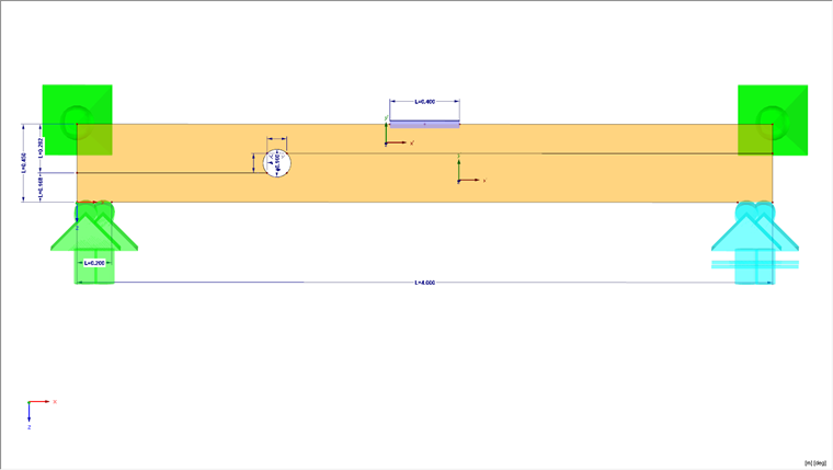
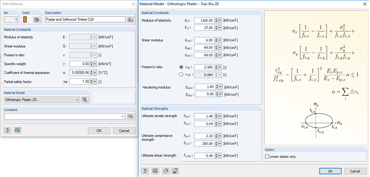
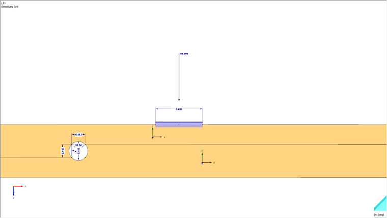
The beam should have the dimension of 4,000 mm, the height is 450 mm, and the width is 120 mm. The simulation should be performed with a hole diameter of 0.4 ∙ beam depth. C24 timber is used as a material, and the orthotropic plastic material model is used as a material model; this represents the wooden composite. The crack simulation is modeled using a line release.
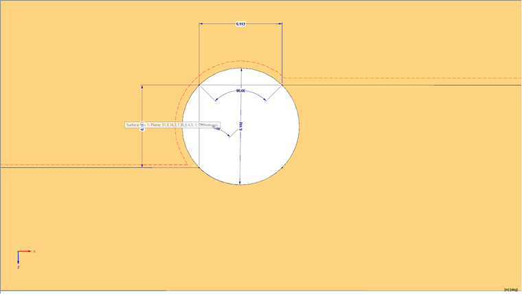
The expected crack in the model occurs with an offset of 45° with reference to the center of the circle at the edge of the opening. The crack is formed along the fiber and can thus be regarded as rolling shear failure. The line release acts as an interface element where a double line is simulated, which is coupled via contact properties. For the contact properties, the material properties according to Section 4.4 are used in [1] in the model. The material properties are actually calculated in advance as diagrams for the line release and then assigned to the line release.
Line Release Definition
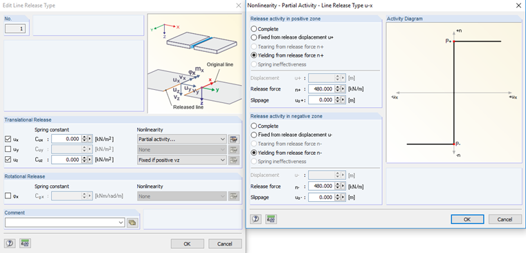
In order to assign the material properties to the line release, the program creates nonlinear joint properties. For this purpose, a diagram is used in our example. To consider the rolling shear correctly, one diagram is created for the shear failure (along the local line axis x) and one diagram for the transversal tension failure (local z-axis of the line). In this case, the shear failure can be spread in the positive and the negative X-direction, while the transversal tension failure is described in the diagram by the values in the fourth quadrant (that is, tensile failure). A value of 0.04 kN/cm² is used for the transversal tension failure and 0.4 kN/cm² for the shear failure. The failure energy is taken from [1] (transversal tension failure G = 220 N/m, shear failure = 780 N/m). Since the material parameters cannot be entered directly in the model, the diagrams must be converted to a line force. This requires a material thickness of 120 mm. For the purpose of simplification, the following properties are defined for the hinge release. In the direction of the local z-axis, the load transfer is only considered for the compression, and along the x-axis, the load of 480 kN/m is applied.
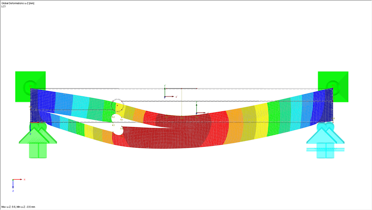
Boundary Conditions
The structure is supported by line supports in the bottom area to clearly consider the support width of the structure. In addition, one of the line supports can only transfer the compressive forces in order to consider the one-sided takeoff in the calculation. In the upper corners, the structure is kept out of the plane to avoid considering the overturning in the calculation.
Loading
A concentrated load of 100 kN is applied to the middle of the structure. To avoid possible singularities in the load introduction point, a member is used for the distribution of the concentrated load into the surface.
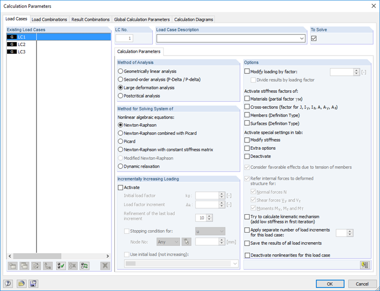
Calculation
Due to the high nonlinear degree of the model, the calculation is performed according to the second-order analysis. RFEM uses the Newton-Raphson solver, a tangent method for calculating the equilibrium state. The FE mesh settings have been globally adjusted to 2.5 mm in the model, which allows for a precise result evaluation and a better localization of the failure (crack) area.
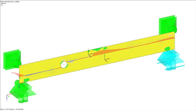
Evaluation
After the calculation, you can see a clear cracking of the structure in the hole area. If you place a section on the crack openings, you will obtain very small values for the internal forces ny in this area, as the opening arises here and thus no more loads can be transferred. These values then bulge again in the rear area, as the crack opening is not yet available there and the load can be transferred in this area. However, there are still the small values for ny in the crack area. They result from the internal stress of the structure, since the transversal tension cannot be excluded completely due to the modeling in the crack area. This transversal tension arises due to the bending of the beam.
This example illustrates how powerful RFEM can be in the area of nonlinear contact conditions (interface elements), and that RFEM can also be used in research.