


The following design example corresponds to H.6 in AISC Design Examples V15.0 [1].
Model Data
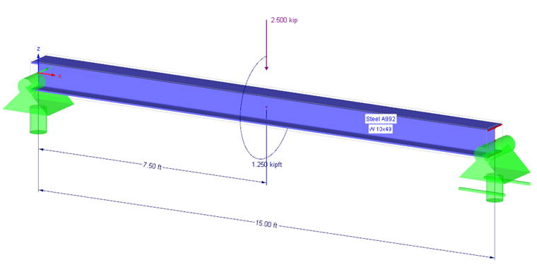
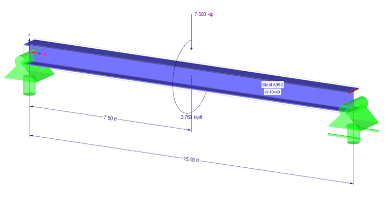
In this example, the beam W10x49 made of ASTM A992 with a span of 15 ft is loaded by eccentric single loads in the center. The loads act with an eccentricity of 6 in. The eccentricity of the load is covered by a torsional moment.
- Load Case 1 Dead (Self-Weight)
- Load Case 2 Live (Variable Loads)
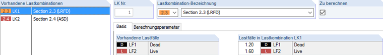
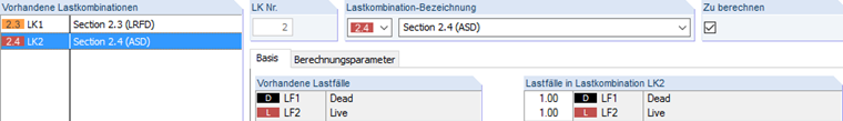
One load combination each is created for LRFD and ASD.
- Load Combination 1: 1.20 LC1 + 1.60 LC2
- Load Combination 2: 1.0 LC1 + 1.0 LC2
Since the design with RF-STEEL Warping Torsion is intended for sets of members, it is necessary to create a set of members.
Design in RF-STEEL AISC with RF-STEEL Warping Torsion
In Design Case 1, the design should be performed according to LRFD 2016. Load Combination 1 is thus selected for the design, and the set of members is selected. The warping torsion analysis is activated under "Details" → "Warping Torsion". Different options are available for load input and method of analysis.
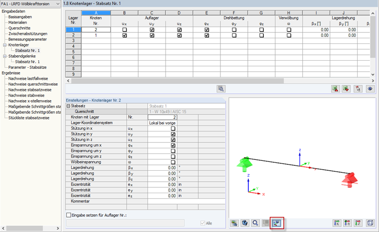
The calculation should be performed for the comparison manually linearly according to the linear static analysis, and the load application should be carried out at the top flange. The subsequent tables can be confirmed up to Input Table "1.8 Nodal Supports". The nodal supports have to be defined here. Together with the member hinges, they form the boundary conditions to determine the critical load factor. The nodal supports can be checked graphically in the partial view. Two lateral and torsional restraints are planned for the beam to be considered in the design.
The calculation can be performed afterwards.
Evaluation of Results and Comparison
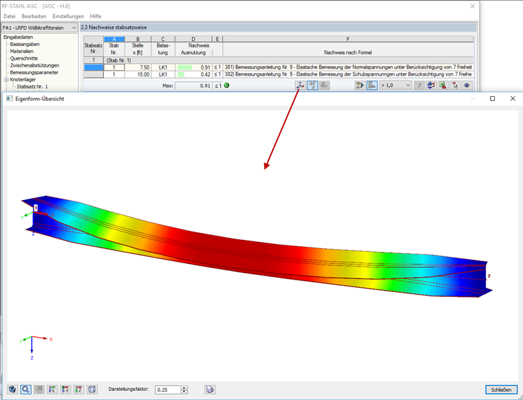
After the calculation, the critical load factor as well as the single stresses are displayed. The determined mode shape can be opened in a separate window and with the graphical display, you can control the boundary conditions.
In the event that lateral-torsional buckling governs, the yield stress Fn is automatically reduced. In the design example, lateral-torsional buckling will not govern and thus the yield stress of material A992 is assigned with Fy 50 ksi.
A comparison with the verification example shows that the same design points of RF-STEEL AISC Warping Torsion are recognized as governing and thus appear in the table.
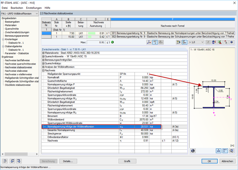
For the design according to LRFD, normal stress of 28.531 ksi is calculated for Stress Point 1, specified with 28.0 ksi in the manual calculation of the verification example.
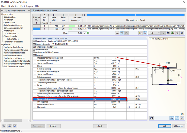
The shear stress design at the support leads to the total shear stress of 11.282 ksi, compared to the manual calculation of 11.4 ksi.
The design can be performed according to ASD as in the previous steps. The maximum normal stress for the design according to ASD is determined with 27.293 ksi at Stress Point 1 for the mid-span. The manual calculation corresponds well with 26.9 ksi. The maximum shear stress over the web at the support is determined in RF-STEEL Warping Torsion with 7.522 ksi, whereas the manual calculation shows 7.56 ksi.
Conclusion
The design is possible for this verfication example. The calculation according to the warping torsional analysis with 7 degrees of freedom allows cost-efficient design of structural components with a risk of warping torsion according to Design Guide 9 [2] of AISC.