


The following article describes the necessary inputs. In addition, the effects of this export on further design checks (for example, stability analysis of reinforced concrete columns) will be shown.
Designed Structural System
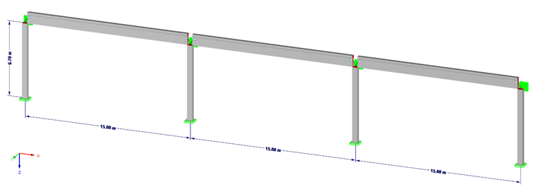
The reinforced concrete column structural system shown in Image 01 is the example for this article. It is a structural system consisting of four cantilever beams, which are rigidly fixed at their footings around the X- and Y-axes. The four cantilever beams are connected with each other by means of hinged beams (beams with member hinges). At the coupling points, the structural system is supported by a point-like support in the global Y-direction, because in this example, only the buckling in the global X-direction will be analyzed. The model file with the individual cross-sections is available for download at the end of this article.
Load Combinatorics and Loading
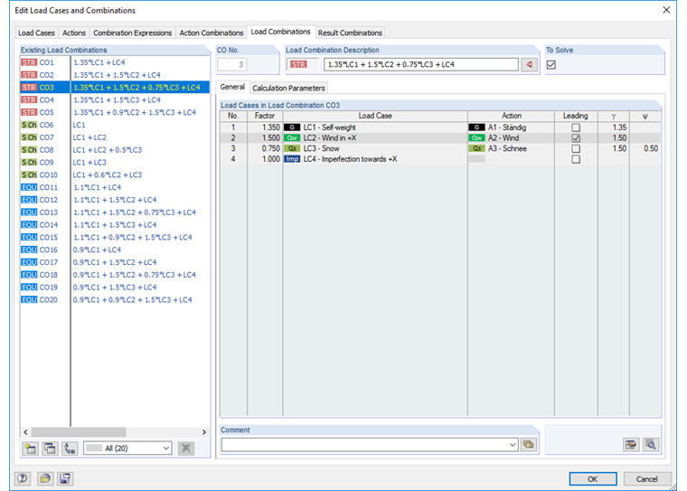
Four load cases will be considered:
- Load Case 1 = Self-weight
- Load case 2 = Wind in + X
- Load case 3 = Snow
- Load case 4 = Imperfection in +X
In RFEM, load combinations according to EN 1990 can be created automatically for the design situations of ultimate limit state, serviceability limit state, and equilibrium limit state. For this example, load combinations are necessary because a calculation according to the second-order analysis is to be performed, taking into account the effective stiffnesses in state II of the reinforced concrete columns. The effects of the second-order analysis and imperfection are deactivated for the serviceability limit state design of the load combinations.
The model file below this article indicates the load applied in the individual load cases.
Designing Reinforced Concrete Columns
In the first step, the internal forces of the individual load combinations are calculated (linear-elastic determination of internal forces). They are applied afterwards for the design in RF-CONCRETE Members. In the RF-CONCRETE Members add-on module, a design case is created where the reinforced concrete columns are designed. For the ultimate limit state design, the "Nonlinear calculation (state II)" option is selected here.
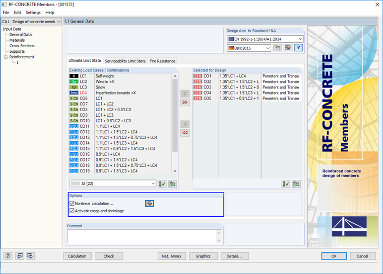
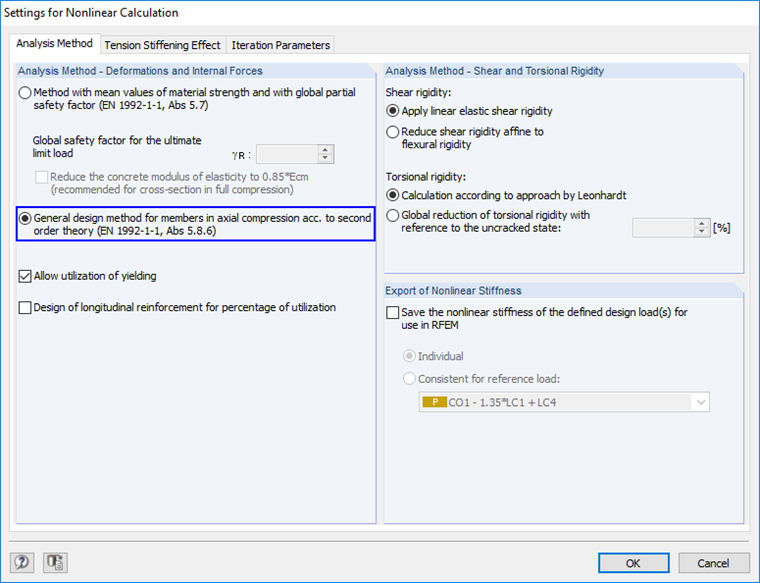
In the settings for the nonlinear calculation, the option "General design method for members in axial compression according to second order theory (EN 1992-1-1, 5.8.6)" is selected.
With the settings mentioned above, RF-CONCRETE Members first calculates a statically required reinforcement from the cross-section design with the internal forces of the COs (linear-elastic design). Finally, a reinforcement proposal is created from the required reinforcement and the user specifications for a basic or minimum reinforcement, which is then used for the nonlinear design.
In this example, the columns are reinforced with a reinforcement of 4 Ø 20 on each side of the cross-section.
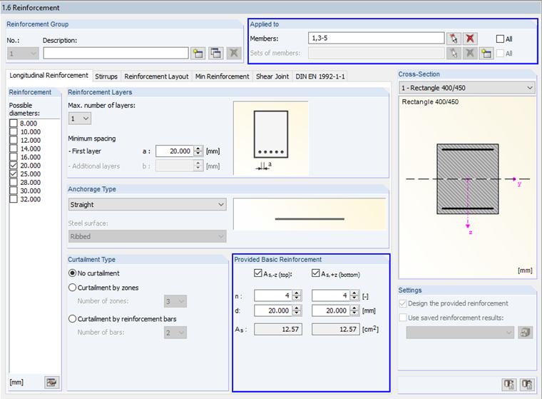
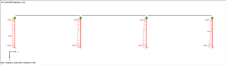
The resulting reinforcement proposal is used for the nonlinear design. RF-CONCRETE Members now calculates the existing safety gamma in state II and alternatively provides an effective ratio 1/gamma of the members.
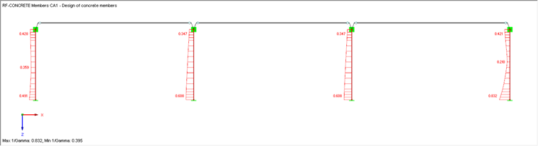
Please note that the results of this nonlinear calculation have been determined on the basis of the provided reinforcement. However, it is impossible to conclude from the displayed design ratio and the provided longitudinal reinforcement that the design ratio is greater and the number of longitudinal bars is reduced at the same time. If the number, position, or cross-section of the longitudinal reinforcement is adjusted, it is essential to recalculate the nonlinear design.
Design of Foundation Plates
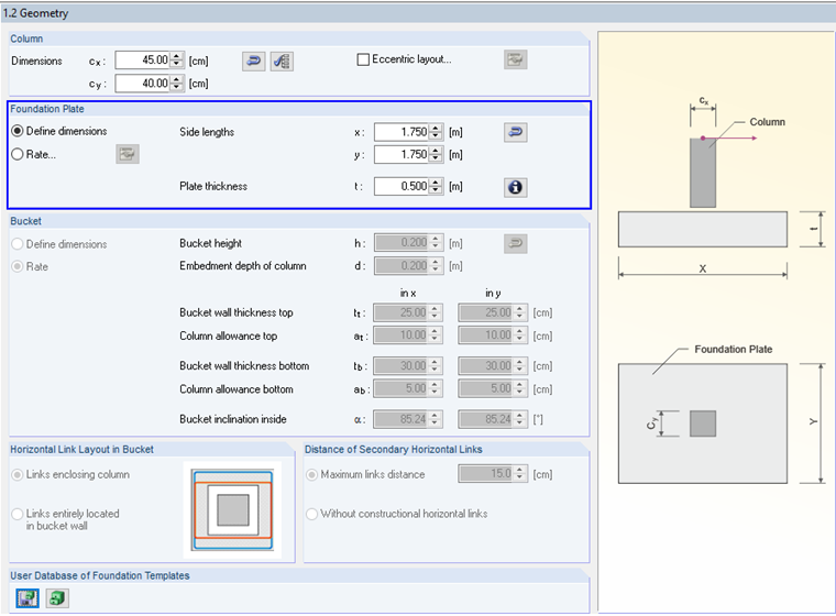
Foundation plates are now designed for the rigid cantilever beams. The RF-FOUNDATION Pro add-on module is used here. The foundation plates have the following dimensions:
- Length = 1.75 m
- Width = 1.75 m
- Height = 0.50 m
The bearing resistance is determined according to DIN EN 1997-1, Annex D. A gravel-sand-silt mixture is the basis for determining the bearing resistance that is preset in the parameters for the soil profile in RF-FOUNDATION Pro by default.
The determination of the bearing resistance in RF-FOUNDATION Pro is described in this technical article.
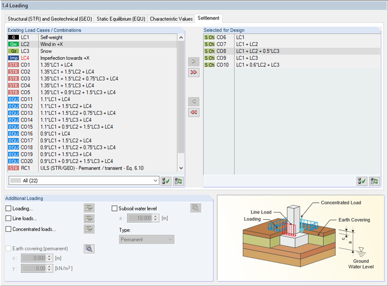
To be able to determine the spring stiffnesses for the foundation plates in RF-FOUNDATION Pro, first you have to activate the settlement calculation in the [Details] settings. In the details settings for the settlement calculation, you can use the calculation option for an elastic foundation or a solid foundation plate. To determine the spring stiffnesses and export them into the RFEM model, select the calculation as a solid foundation plate.
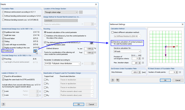
By activating the settlement calculation, the "Settlement" tab becomes available in Table "1.4 Loads". In addition to the generated COs for the limit states STR, GEO, and EQU, you have to define the load for which the settlements should be determined in Table "1.4 Loading", "Settlement" tab. In this case, the COs are taken from the characteristic design situation. Accordingly, the program also requires a horizontal force or a support moment to determine the foundation rotation or rotational spring stiffness. This must be considered when selecting the relevant COs for the design.
After the calculation, you can find the results of the settlement calculation in Result Table "2.2 Governing Design Criteria" in addition to all other design checks (equilibrium limit state, ground failure, highly eccentric loading in the core, bending design of the foundation plate, and so on). In the detail tables, it is now possible to see the spring stiffnesses for each node and each calculated load combination in the z-direction as well as the spring constants Cφ,x and Cφ,y.
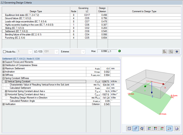
Image 10 shows that the spring constant Cφ,x could not be determined. This is because in the example considered here, no rotation around the X-axis is calculated (2D frame structure, moments around the Y-axis only).
The spring constants now available from the settlement calculation can be exported using the File menu in RF-FOUNDATION Pro.
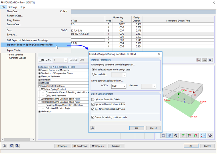
After the spring stiffnesses have been exported, new nodal supports are available in RFEM that contain these spring stiffnesses. By applying these new nodal supports, the results from RFEM and the RF-CONCRETE Members as well as the RF-FOUNDATION Pro add-on modules are deleted.
Recalculating the Reinforced Concrete Design with Spring Constants from RF-FOUNDATION Pro
Since the results have been deleted by exporting the spring stiffnesses, the calculation of the results in RF-CONCRETE Members must be restarted. The entries in the add-on module (mesh reinforcement, and so on) initially remain unchanged, as described above.
A new nonlinear calculation of the columns results in a ratio > 1.00 with the previously set provided reinforcement. The difference in the modified design ratio of the reinforced concrete columns results from the spring stiffness from RF-FOUNDATION Pro exported into the RFEM model and the redistributing effect from the nonlinear calculation.
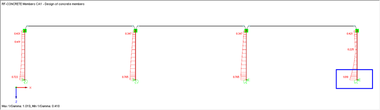
In the next step, a new reinforcement group can be selected for those members in RF-CONCRETE Members that have a design ratio > 1.00 and the number or diameter of the longitudinal reinforcement is, for example, incremented in this reinforcement group.
Alternatively, you can also increase the number of longitudinal bars for all columns by n = 1. This would result in the following ratio in the present example.
Exporting Stiffnesses of Columns in State II
Furthermore, in RFEM it is also possible to export the stiffnesses in state II from the column design in RF-CONCRETE Members into the RFEM model. Thus, it is also possible to use the stiffnesses from state II of the reinforced concrete design and the spring stiffnesses from the foundation design for another determination of the internal forces and design results.
This present example does not describe exporting stiffnesses in state II. Find more information about it in this Knowledge Base article:
Conclusion
As you can see in this example, exporting spring stiffnesses from a settlement calculation in RF-FOUNDATION Pro can have a significant influence on further design checks. Thus, we recommend considering applying realistic stiffnesses for nodal supports instead of using a rigid support.
When using RFEM, the structural engineer has the possibility to easily check these influences and analyze them in a model file.
Note: This article was written for the analysis in RFEM 5. The option to export spring constants from FOUNDATION Pro is also available in RSTAB 8. The approach described here can be carried out in the same form in RSTAB 8.