


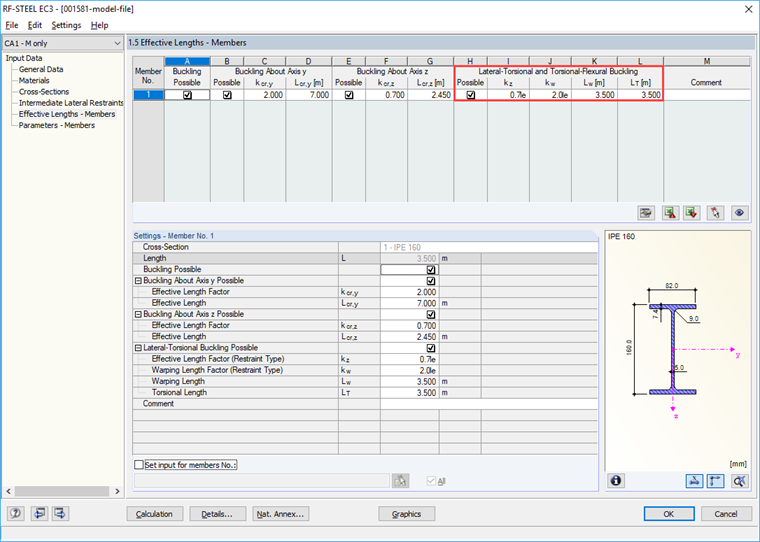
My previous article showed the effects of the lateral intermediate supports as well as the effective lengths Lcr,y/z.
The parameters for lateral-torsional buckling additionally include the lengths Lw and LT as well as the effective length factor kz and the warping length factor kw for a more detailed definition.
Effective Length Factor kz
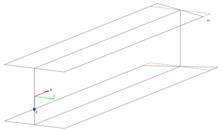
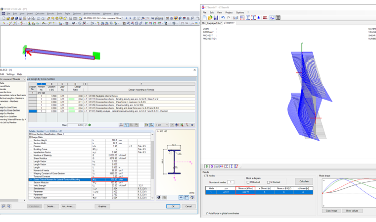
An internal eigenvalue solver can be used to determine the ideal lateral-torsional buckling moment. It requires an internal member model with four degrees of freedom (uy, φz, φx, ω).
The factor kz controls the support at the member start and member end with regard to the degrees of freedom uy (displacement in y) and φz (rotation around z). In this example, both parameters are fixed at the member start. At the member end, it can only be assumed that the displacement in uy is restricted. This situation corresponds to the definition kz = 0.7le.
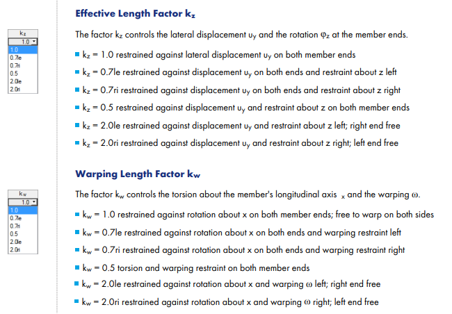
Warping Length Factor kw
This parameter is also used to support the internal member model. It controls the two remaining degrees of freedom φx (rotation around x) and ω (warping). Due to the restraint of the beam, both degrees of freedom are fixed at the start. At the free end, neither φx nor ω will be fixed. This corresponds to the definition kw = 2.0le.
Warping Length Lw
The warping length is included in the determination of Mcr. It corresponds to the distance of the lateral and torsional restraints and is thus not necessarily identical to the effective length Lcr,z. This also becomes apparent when comparing the elastic critical moments Mcr between RF-/STEEL EC3 and LTBeamN (a program to determine critical loads).
The effective length Lcr,z = 0.7 ⋅ L (analogous to Euler Case 3). In contrast to this, the warping length is applied with Lw = L. In RF-/STEEL EC3, the Mcr for this results in 105.90 kNm. This corresponds to the result of the program LTBeamN, which calculates Mcr = 105.77 kNm. Compare: Using the warping length of 0.7 ⋅ L would have resulted in Mcr = 174 kNm.
Torsional Length LT
The torsional length is the governing length for the torsional buckling analysis according to 6.3.1.4 [1]. It is performed for compressive force only. It has no effect on the lateral-torsional buckling analysis. In the example, it is applied equal to the member length.
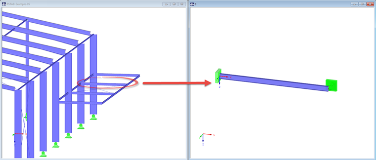
Comparison with Input by Means of Nodal Supports Analogous to Window 1.7
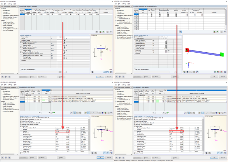
By designing sets of members according to 6.3.4 [1], RF-/STEEL EC3 offers the possibility to define the internal member model directly by means of nodal supports. The four degrees of freedom are available here. In the following comparison of the input options, we want to clarify that it is possible to have the same result. The structural system will remain identical for this purpose. Only the loading as well as the cross-section will be changed. Instead of IPE 160, a simple symmetric T-section is selected. Thus, the design according to 6.3.4 [1] will be necessary. In the image below, you can see a comparative overview of the input by effective lengths on the left and by nodal supports on the right. The result proves the assumption made at the beginning.
Conclusion
RF-/STEEL EC3 generally assumes a single-span beam with lateral and torsional restraint. The default parameters are aligned with it. With these preset factors, the user has the option to display other structural systems. It is finally up to the user to decide which degrees of freedom will remain in the respective nodal points.