


This article shows an example of how these two governing parameters are entered and explains their effects on the results. We take a closer look at the following structure.
Structure
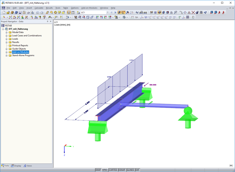
A steel beam with a length of 6 m has lateral and torsional restraint at both ends. A coupling member is connected perpendicularly in the middle of the member. It does not introduce any force into the structure, but only serves as a support against lateral buckling. The main beam is subjected to uniaxial bending and compression.
The design is carried out in RF‑/STEEL EC3. The focus is placed on the design according to 6.3.3, the uniform structural elements subjected to bending and compression. Several module cases are analyzed by specifying the boundary conditions on a case-by-case basis. The aim is to point out the effects of the settings on the calculation. A set of members is defined for the main beam that is selected for the design. Since the module always assumes a single-span beam with lateral and torsional restraints regardless of the given situation, the correct member length of 6 m is entered for the vertical buckling.
Case Study
Case 1: Design of Set of Members Without Intermediate Support
The lateral support will not be considered in the first case. No manual adjustments are necessary. The effective lengths are included in the calculation with 6 m, which was set automatically.
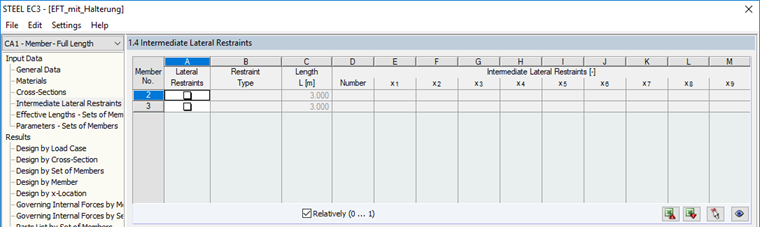
The input window for the lateral intermediate supports remains unaffected.
The elastic critical load for buckling around the z-axis Ncr,z as well as the elastic critical moment for lateral-torsional buckling Mcr are taken to compare the results. These intermediate results are included as governing in the calculation of the reduction factors Χz and ΧLT, as well as the interaction factors kyz and kzz, which can be found in the design formulas according to 6.3.3. In Case 1, they result in:
Ncr,z = 347.6 kN
Mcr = 78.7 kNm
Design ratio = 99%
Case 2: Design of Set of Members with Adjusted Effective Length Lcr,z = 0.5 ⋅ L
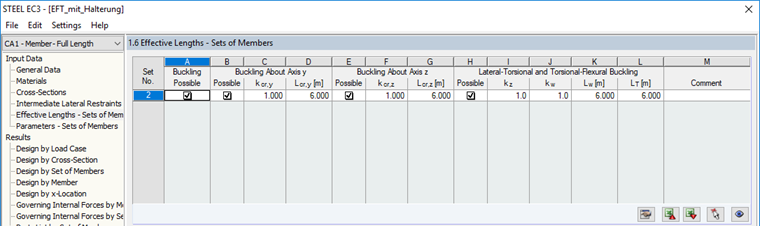
Case 2 considers the fact that the main beam will not buckle around the z-axis in its full length due to the coupling member, but is likely to have a sinusoidal buckling mode. Therefore, the effective length Lcr,z is reduced to 0.5 ⋅ L = 3 m in Window 1.6. However, no data have yet been entered in the intermediate lateral restraint.
Ncr,z = 1,390.5 kN
Mcr = 78.7 kNm
Design ratio = 77%
It is clear that the elastic critical buckling load Ncr,z is increased due to the effective length modification. In other words, this means that by halving the effective length, the member would not buckle laterally until the axial force was far greater. It is also apparent that Mcr remains the same. It can be concluded that an adaptation of the effective length does not change the structural system (which is the basis for the calculation of Mcr).
Case 3: Design of Set of Members with Definiton of Intermediate Lateral Restraint uy at 3 m
Based on Case 1, only one intermediate lateral restraint is defined in Window 1.4 for Case 3. A user-defined support at the end of Member 1 is applied while only activating the lateral support uy. As in Case 1, the effective lengths are 6 m.
Ncr,z = 347.6 kN
Mcr = 187.0 kNm
Design ratio = 76%
Compared to Case 2, it is clear that the definition of the lateral intermediate support has an effect on Mcr. The structural system has been changed in the background from a simple single-span beam to a single-span beam with a lateral support in the center. It can also be stated that the definition of the intermediate lateral restraint does not necessarily have an effect on the elastic critical buckling loads. Ncr,z corresponds again with the result from Case 1.
Case 4: Design of Set of Members Including Intermediate Lateral Restraint and Adjusted Effective Length
In Case 4, the adjustments of Case 2 and Case 3 are combined. This results in the following intermediate values:
Ncr,z = 1,390.5 kN
Mcr = 187.0 kNm
Design ratio = 53%
They are based, as expected, on the results of the two previous cases. Due to the combination, the design ratio is, however, reduced again from 76% and 77% to 53%.
Summary
Even if the development of the ratio through the cases can only be displayed as a snapshot for this special case, it should be emphasized that the member as a whole has to be considered correctly for the design. This means that the effective lengths are checked and the internal structural system is supported adequately. In this example, only the effective length around the z-axis and the support by lateral intermediate restraints were described in detail. If the basic structure is not a single-span beam with lateral and torsional restraints at the end points, the support conditions have to be defined in detail here. Find more information about this in the manual or the articles linked below.