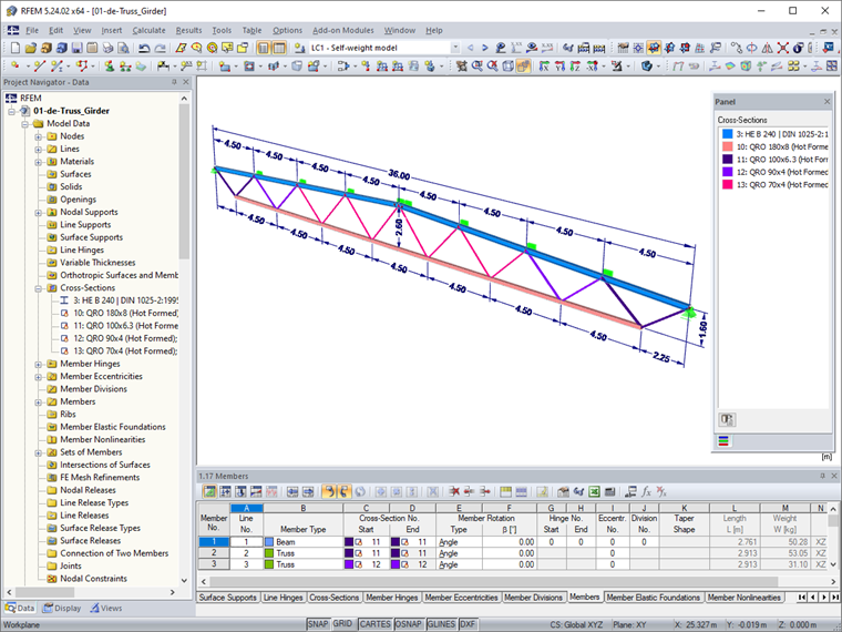
The model is based on Example 1.4, to be found in the technical literature [1]. Image 01 shows the structural system with dimensions as well as the display of the cross-sections used.
Actions and Design Internal Forces
The characteristic actions for this partial structural system are summarized in [1] and transferred to the corresponding load cases. A load generation on the 3D model is certainly more realistic and preferable for this building. The combinations of the ULS and SLS design situations are generated automatically in RFEM or RSTAB.
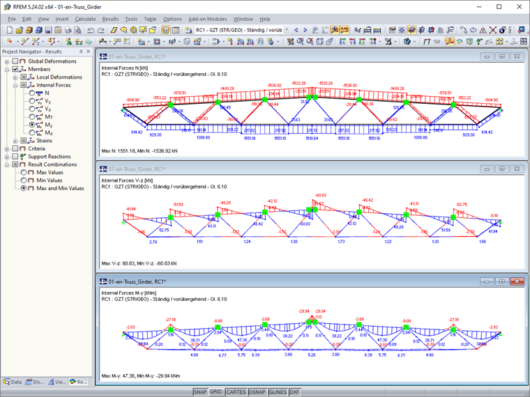
The internal forces and moments, as well as deformations in the load combinations, are calculated according to the linear static analysis. This results in the following design internal forces and moments for the ultimate limit state design (Image 02).
Cross-Section Classification
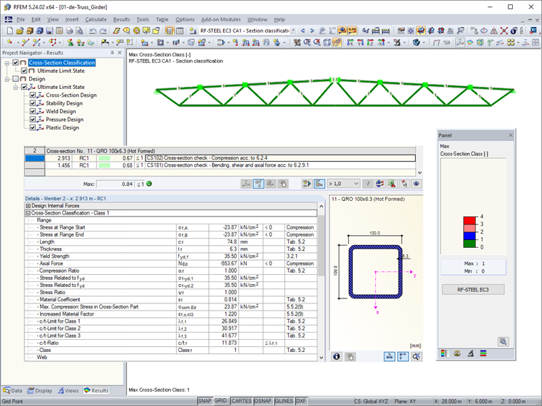
To determine the cross-section class, a first design case is created in RF-/STEEL EC3 for all members and without stability design checks. The cross-section class is calculated by the x-location for the available internal forces. A graphical display of the resulting cross-section class is available via the Results Navigator (Image 03). All cross-sections are in cross-section Class 1; thus, the plastic cross-section design according to Section 6.2.9 in [2] is possible.
Ultimate Limit State Design
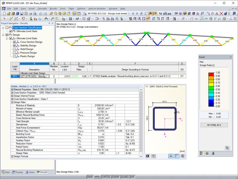
Now, the cross-section and stability analyses for the internal members as well as the upper and lower chords are carried out. To design the internal members (Member 1 through Member 16), a second design case is created in RF-/STEEL EC3. The stability analysis is performed according to Section 6.3.1 in [2]. The effective length factor for the major and minor axes is set to 0.75, according to Section BB.1.3 (3) B in [2]. See the design ratios in Image 04.
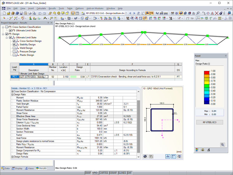
For the design of the bottom chord, a third design case is created in RF-/STEEL EC3. Since there are also tensile forces in the bottom chord under wind suction, only cross-section design checks are required. Furthermore, it is not necessary to perform the design with a net cross-section, as the internal members are welded to the chords, and thus there are no holes in the cross-section. See the design ratios in Image 05.
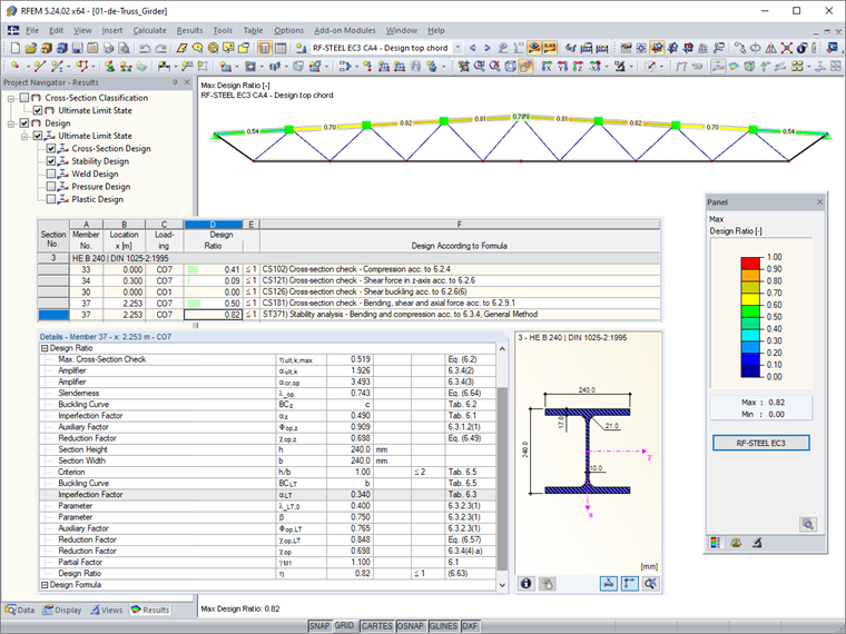
To design the upper chord, a fourth design case is created in RF-/STEEL EC3 and the corresponding set of members is selected. In contrast to [1], the design is performed by the general method according to Section 6.3.4 in [2] to better represent the boundary conditions. A lateral and torsional restraint is assumed on the supports. No lateral or torsional restraint can be assumed at the purlins' connection points on the upper chord. A lateral support is applied to the upper chord and a rotational spring, which results from the HE-B 240 cross-section deformation. See the design ratios in Image 06.
Serviceability Limit State Design
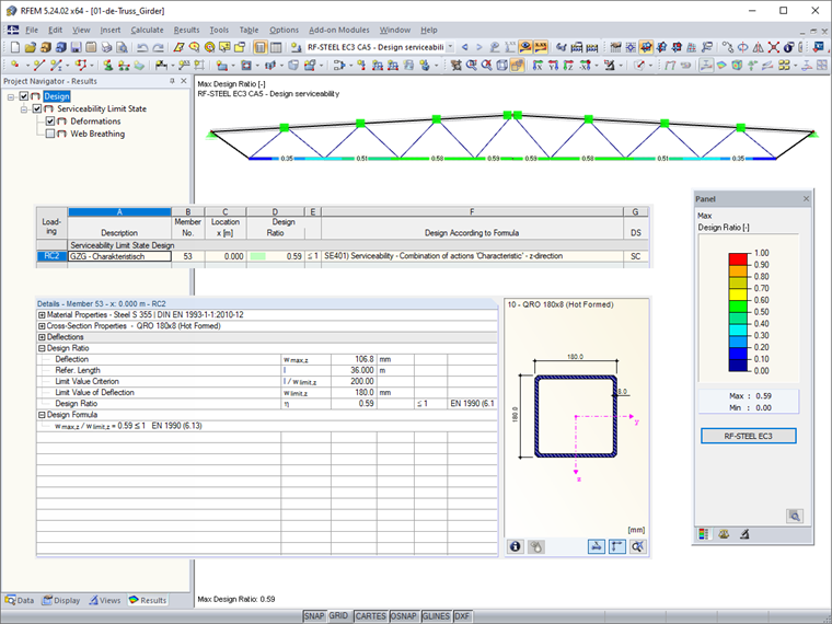
For the design of the lower chord, a fifth design case is created in RF-/STEEL EC3. In this case, only the load combinations in SLS are selected. In [2], no information about allowable deformations is given. They must be coordinated with the customer on a project-specific basis. Therefore, this analysis is geared to the limit value of L/200 mentioned in the prestandard. See the design ratios in Image 07.
Design of Connections
Designing the welded connections of the chord nodes as well as the connection of the truss to the restrained external supports is not described in this article. The design of the end plate connection in the bottom chord according to the CIDECT method and using the FEA model is explained in detail in this technical article: