Software Limitations
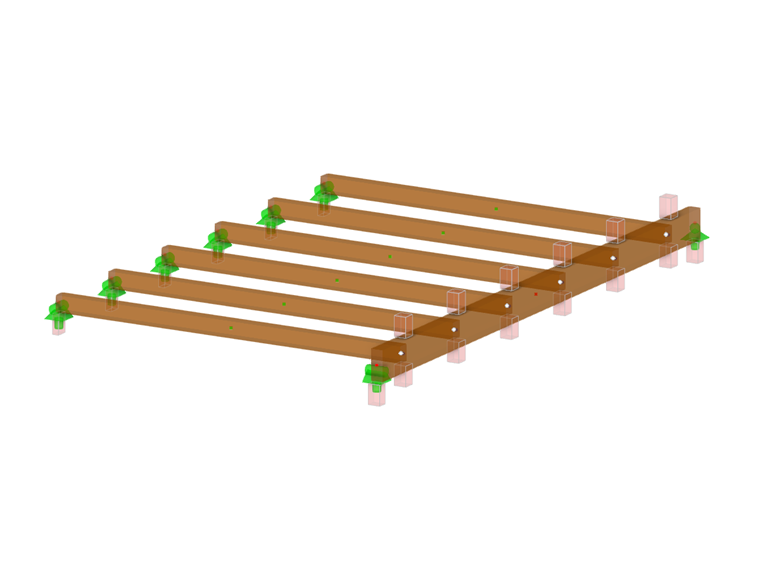
In all general FEA design programs including RFEM, each member is represented by a single line element located at the section’s centroid. This is referred to as the wireframe rendering view. The member includes internal information such as the material properties as well as the geometric properties including width and height to be used in both the analysis and design calculations. However, when intersecting members are modeled, the program has no immediate information such as how the intersecting members are oriented relative to each other or in the case of members bearing on one another, the bearing area is unknown. The program is only aware of these line elements connected at a single nodal point.
When small members are connected to larger girder members by bearing down at the top face or when members are supported at either end or along the length by a bearing support type, the member stress perpendicular to the grain should be included in the design checks. The NDS Sec. 3.10.2 [1] and CSA O86 Clauses 6.5.7 and 7.5.9 [2] design checks for bearing perpendicular to the grain both require the net bearing area to be known. Because of this requirement, design software may forgo important factors such as the bearing area factor, Cb, [1] or the length-of-bearing factor, KB, [2], or the design check is ignored altogether.
With the new RFEM 6 feature "design supports", it is now possible to define such information and carry out the full design checks for compression stress perpendicular to the grain.
NDS 2018 Workflow
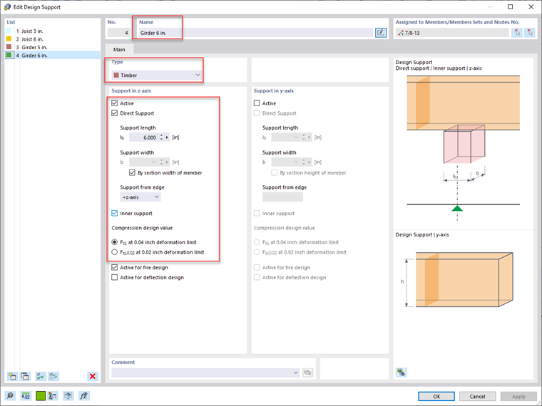
When creating a new design support definition, the Type should be set to "timber". This will activate the relevant input data according to the NDS standard. The Direct Support checkbox indicates this definition type will be used for the compression check perpendicular to the grain. The Support Length is user-defined and should specify the total length of the bearing area. The Support Width is automatically set as the width of the relevant member, but can be overwritten. Support from Edge indicates whether the bearing support is located at the upper +z axis of the member, the lower -z axis, or both. The Inner Support checkbox indicates whether the Cb factor should be applied to the member’s compression design value perpendicular to the grain, Fc⟂, based on Sec. 3.10.4 [1]. If this option is checked off, an end support will not consider Cb. The member’s Compression Design Value set forth in the NDS varies depending on the deformation limit selected.
Once the design support input information is complete, the design supports can be applied to the relevant nodes and members on the structure. Multiple design supports may be needed, as different bearing scenarios may occur at different locations. RFEM allows the user to set a user-defined Name for multiple design support definitions at the top of the dialog box for quicker and more convenient applications.
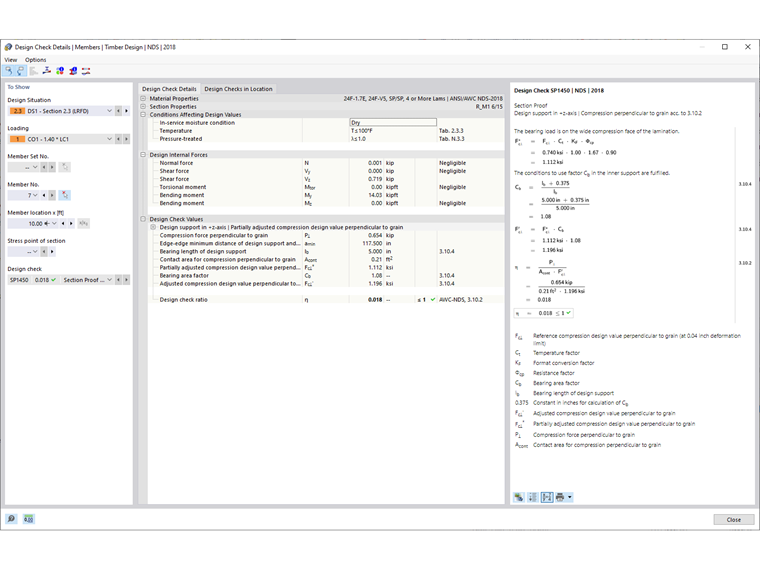
The section proof will be carried out in the Timber Design add-on considering Sec. 3.10.2 [1]. With a glued-laminated member, for example, the adjusted compression design value perpendicular to the grain, Fc⟂’, is defined in Table 5.3.1 [1] with the following equation.
|
Fc⟂ |
Reference compression design value perpendicular to the grain |
|
CM |
Wet service factor |
|
Ct |
Temperature factor |
|
Cb |
Bearing area factor |
|
KF |
Format conversion factor (LRFD only) |
|
φ |
Resistance factor (LRFD only) |
The Cb factor is further defined in Sec. 3.10.4 [1]. However, Cb is only applicable if the Support Length defined under the Design Support definition is less than 6 inches and farther than 3 inches to the end of a member. Additionally, Cb is only applicable for inner supports, which also must be indicated under the definition type as indicated above. If these criteria are met, the Timber Design add-on will automatically calculate and apply Cb based on the following equation.
The section proof design check ratio is determined by the ratio of the demand compression force perpendicular to the grain to the adjusted compression design value perpendicular to the grain. All NDS variables, formulas, and code references are indicated directly in the Timber Design add-on design check details providing clear and traceable results.
CSA O86:19 Workflow
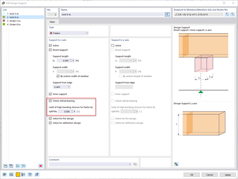
When designing according to CSA O86:19, the same workflow above for the NDS can be followed for the design support definition type. There are a few key differences with the CSA standard, however. A new option, Check Critical Bearing, will determine if the compression load is applied within a distance from the center of the support equal to the depth, d, of the member indicated in Fig. 6.2 [2]. If so, the factored compressive resistance perpendicular to the grain is reduced by a factor of 2/3 as shown in Clause 6.5.6.3.1 [2] for sawn lumber and Clause 7.5.9.3.1 [2] for glued-laminated timber. The average bearing area should also be used.
The Limit of High Bending Stresses for Factor Kb is also set in the design support definition type. The length of the bearing factor, Kb, can be applied to the compressive resistance if the bearing area does not occur in positions of high bending stresses indicated in Clause 6.5.6.5(b) [2]. The user can set the ratio of demand moment to moment capacity to be considered a high bending area.
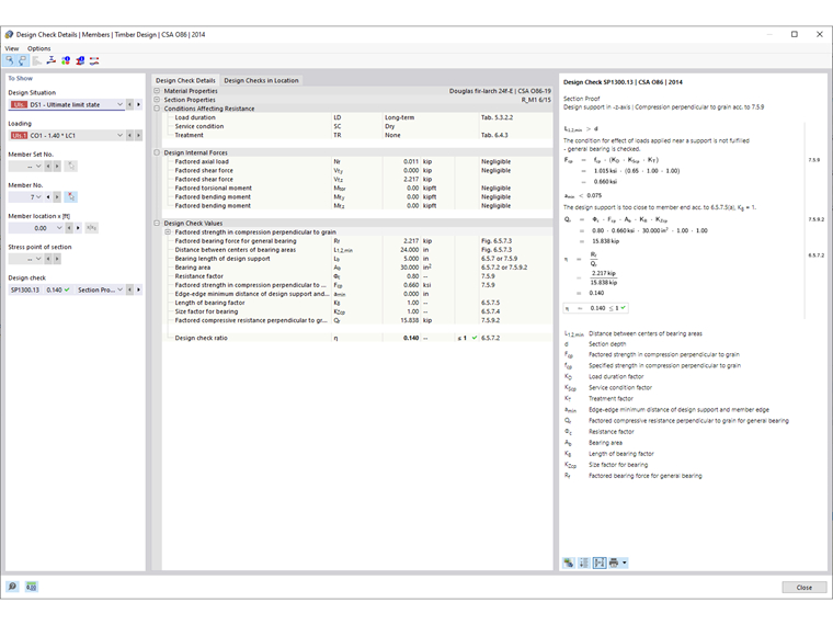
With a glued-laminated member, for example, the factored compressive resistance perpendicular to the grain, Qr, is defined in Clause 7.5.9.2 [2] with the following equation.
|
Φ |
= 0.8 |
|
Fcp |
= fcp(KDKScpKT), where fcp is the specified strength in compression perpendicular to the grain, |
|
Ab |
Bearing area |
|
KB |
Length-of-bearing factor |
|
KZcp |
Size factor for bearing |
The section proof design check ratio is determined by the ratio of the demand factored bearing force to the factored compressive resistance perpendicular to the grain. All CSA O86 variables, formulas, and code references are indicated directly in the Timber Design add-on design check details.
Summary
Bearing stresses perpendicular to the grain are an integral part of member design according to both NDS 2018 and CSA O86:19. The bearing area is typically an unknown variable for this design check when using general analysis and design software, as all members are represented by an internal line element connected at nodal points only. However, the new "design support" feature in RFEM 6 now allows users to specify the length and width of the bearing area, paving the way for compression design checks perpendicular to the grain that previously were not possible.