


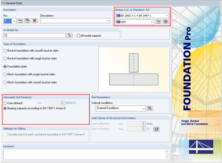
The following example shows this determination. In Window 1.1 General Data, we select the "Bearing capacity according to EN 1997‑1 Annex D" option. The analytical method described herein includes "Method 2", which is preset by default when selecting "CEN" as the NA of the design standard.
Soil Layers and Soil Properties
When determining the bearing resistance, it is necessary to specify a soil profile first, which is to be taken into account for the design. Then, the soil profile in the final state is considered as the analytical determination of the bea resistance is based on this.
In our example, the soil layers adjacent to the foundation (Soil 1') and up to 0.75 m below the foundation base (Soil 2') have the following soil properties:
Specific Weight: γ = 20.00 kN/m³
Angle of internal friction: φk = 28.0°
Cohesion: c'k = 15.00 kN/m²
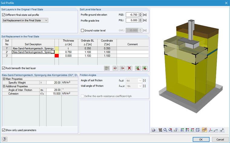
The soil layer below the soil replacement (Soil 3, from the original soil profile) has the following soil parameters:
Specific Weight: γ = 20.00 kN/m³
Angle of internal friction: φk = 32.0°
No cohesion: c'k = 0.00 kN/m²
Foundation Plate Dimensions
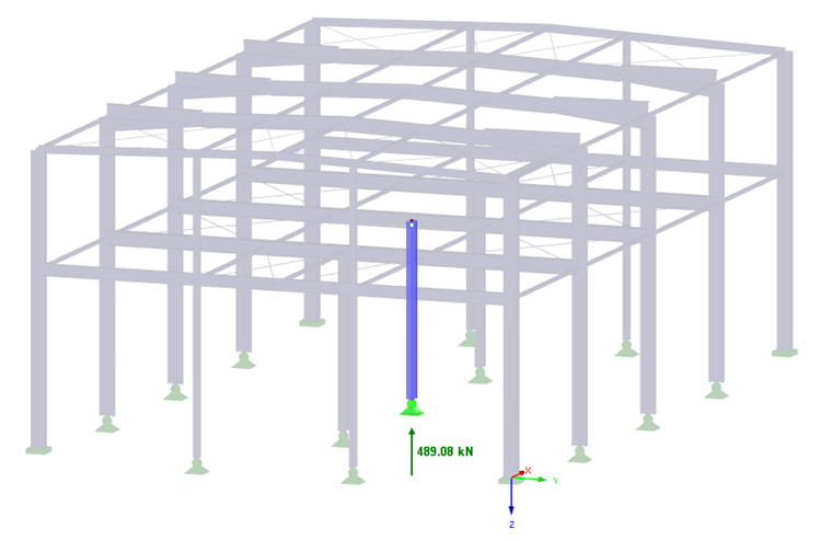
In this example, the calculation of the allowable soil pressure refers to a rectangular foundation plate with dimensions of 1.50 m × 1.50 m × 0.35 m. In the present model, the bearing capacity of a foundation plate of a steel hall is analysed. In the middle of the foundation plate, there is a hinged column of the steel hall, and thus the foundation plate is loaded by the vertical load of Vd = 489.08 kN. Image 03 shows the steel hall column, including the governing support reaction P-Z.
Determination of Bearing Resistance
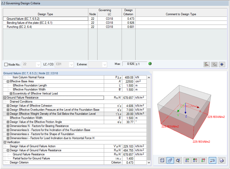
The characteristic value of the bearing resistance can be determined for drained conditions according to [1] Appendix D, Equation (D.2):
In the first step, the effective soil properties are determined initially, as there are two different layers with different soil properties under the foundation base. In this example, the resulting depth of the ground failure cone is zs = 2.443 m. Thus, Soil 3 is under the foundation base with a depth of 2.443 m − 0.75 m = 1.693 m.
Effective soil properties:
γ' = 20 kN/m³
Effective overburden pressure at the level of the foundation base:
q' = 0.35 m · 20 kN/m³ = 7.0 kN/m²
In the next step, the dimensionless factors for the bearing resistance, the inclination of the foundation base, the shape of the foundation, and the inclination of the load caused by a horizontal load are determined.
Dimensionless factors for bearing resistance:
Nq = eπ · tanφ' · tan² (45 + φ' / 2) = 20.096
Nc = (Nq - 1) · cos φ' = 32.069
Nγ = 2 · (Nq - 1) · tan φ' = 22.741
A foundation plate with a square shape is analyzed in this example. Thus, the following dimensionless factors result for the shape of the foundation:
sq = 1 + sin φ' = 1.512
sγ = 0.70
sc = (sq · Nq - 1) / (Nq - 1) = 1.538
In this context, it should be noted that the effective foundation length L' and the effective foundation width B' must be applied to the foundation dimensions. In this case, only the vertical load is examined and the load eccentricity is equal to zero; thus, the result is L' = B' = 1.50 m and the shape is a "square foundation". If a horizontal load is applied to the foundation, a rectangular effective foundation shape would result from the different effective foundation lengths L' and widths B'.
The resulting dimensionless factors for the inclination of the foundation base bc, bq, and bγ are 1.00, as the bearing resistance design in RF-/FOUNDATION Pro is basically performed for horizontal foundation plates (α = 0°). The resulting dimensionless factors for the inclination of the load caused by a horizontal load H are also 1.00 in this case, since no horizontal loads are applied.
Using these input parameters, we can now determine the ground failure resistance according to (D.2):
Design Criterion for Ground Failure Resistance
As already mentioned, this example explains the calculation according to CEN using Method 2. Based on the parameters of the National Annex ([1], Table A.5 in this case), the partial factor for ground failure of γR,v = 1.4 is provided.
Thus, the design value of the ground failure resistance is:
The existing soil pressure V'd / A' results from the sum of the stresses due to the axial force in the column and the self-weight of the foundation plate:
Design criterion:
You can find more information about the calculation of the ground failure resistance in RF-/FOUNDATION Pro, in the corresponding manual. Chapter 8.4 of the manual also describes the determination of the ground failure resistance. Furthermore, the differences between the analysis methods 2 and 2* are explained here.