The Concrete Design add-on allows you to design reinforced concrete members and surfaces according to various design standards. It is possible to perform the ultimate limit state and serviceability limit state design checks. The input and result evaluation are completely integrated in the user interface of the structural FEA software RFEM and the frame & truss analysis software RSTAB.
This manual describes the Concrete Design add-on for RFEM 6 and RSTAB 9. In RSTAB, you can only design members and member sets, not surfaces.
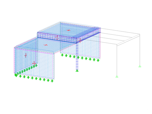
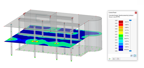
In this tutorial, we would like to inform you about the essential features of the RFEM program. In the first part, a model was defined and a structural analysis was carried out. The second part deals with the concrete design of the slabs, walls, beams, and the column according to EN 1992‑1‑1 with the CEN settings.
In this tutorial, we would like to inform you about the essential features of the RFEM program. In the first part, a model was defined and a structural analysis was carried out. Now, the second part deals with the concrete design of slabs, walls, beams, and the column. ACI 318-19 is used as a standard.
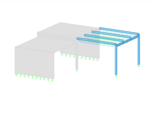
In this tutorial, we would like to inform you about the essential features of the RFEM program. In the first part, a model was defined and a structural analysis was carried out. The concrete design was performed in the second part. Finally, the third part deals with the design of the steel members according to EN 1993‑1‑1 with the CEN settings.
In this tutorial, we would like to inform you about the essential features of the RFEM program. In the first part, a model was defined and a structural analysis was carried out. After performing the concrete design in the second part, the third part now deals with the design of steel members. AISC 360-22 is used as a standard.
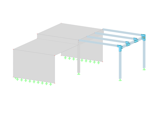
In this tutorial, we would like to inform you about the essential features of the RFEM program. In the first part, a model was defined and a structural analysis carried out. Then the concrete and steel designs were performed in the following parts. This part now deals with the design of the steel connections according to EN 1993-1-8 with the CEN settings.
In this tutorial, we would like to inform you about the essential features of the RFEM program. In the first part, a model was defined and a structural analysis carried out. Then the concrete and steel designs were performed in the following parts. This part now deals with the design of the steel connections according to AISC 360-22.
In this tutorial, we would like to inform you about the essential features of the RFEM program. In the first part, a model was defined and a structural analysis carried out. Then the concrete and steel designs were performed out in the following parts. This part now guides you through the dynamic analysis of the model according to EN 1998-1 with the CEN settings.
In this tutorial, we would like to inform you about the essential features of the RFEM program. In the first part, a model was defined and a structural analysis carried out. Then the concrete and steel designs were performed out in the following parts. This part now guides you through the dynamic analysis of the model according to ASCE 7.
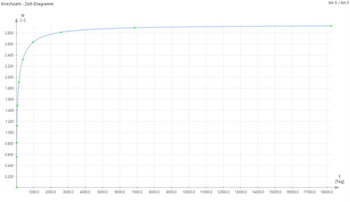
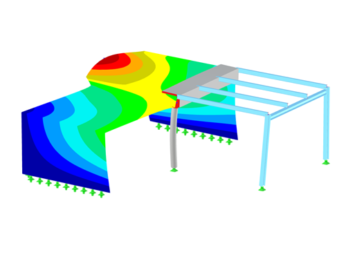
For some structures, the long-term effects, such as creep, shrinkage, and aging, can influence the distribution of internal forces. This time-dependent material behavior can be determined using the Time-Dependent Analysis (TDA) add-on, which is available in the RFEM 6 program.
The influence of the time-dependent material behavior is currently only taken into account for member elements, and creep effects for the material concrete.
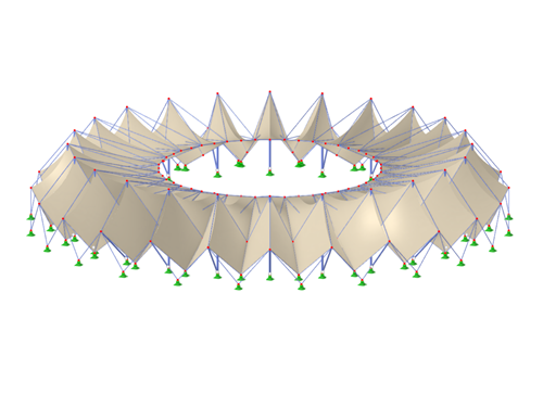
This manual describes the modeling of a stadium roof made of membranes in RFEM 6. Since the model consists of several segments, the creation of the individual segments is shown. Each segment consists of a main structure (a column, a stiffening element, cables) and a secondary structure (a membrane).
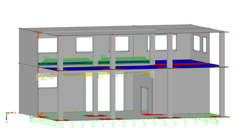
This manual describes the topics of the webinar "Modeling and Design of Reinforced Concrete Structures in RFEM 6 and RSTAB 9".
Using an example of a building ceiling, we explain how to perform reinforced concrete design according to Eurocode 2. Furthermore, the result documentation in the printout report is explained.
In the manual for the Concrete Design add-on, you can find detailed explanations of all the add-on options.

The RF-CONCRETE Members add-on module for RFEM 5 performs the required ultimate and serviceability limit state design checks of reinforced concrete members according to various standards. Optionally, the program checks whether the requirements of the fire resistance design according to EN 1992‑1‑2 are fulfilled.
The manual also describes the RF-CONCRETE NL module extension.

The RF-CONCRETE Surfaces add-on module for RFEM 5 performs the required ultimate and serviceability limit state design checks of reinforced concrete surfaces according to various standards. The allowable maximum and minimum reinforcement ratios for the different structural component types, as well as user-defined basic reinforcement, are also taken into account.
The manual also describes the module extensions RF-CONCRETE Deflect and RF-CONCRETE NL.
.png?mw=500&hash=b33af13b78012d66138c32d36595933cafea9006)
The add-on modules RF-JOINTS (for RFEM) and JOINTS (for RSTAB) combine the connection modules for member elements in a single user interface. Currently, the steel categories Column Base, Pinned, Rigid, Tower, DSTV, and SIKLA, as well as the timber categories Steel to Timber and Timber to Timber, are implemented. This manual describes the special features of all these add-on modules.