- Most Frequently Asked Questions Answered by Dlubal Support Team | June 2023
- RFEM for Students | Part 3
- Most Frequently Asked Questions Answered by Dlubal's Support Team | November 2022
- Most Frequently Asked Questions Answered by Dlubal Support Team | November 2022
- Most Frequently Asked Questions Answered by Dlubal Support Team | February 2023
- Most Frequently Asked Questions Answered by Dlubal Support Team | March 2023
- Result Diagram with Smooth Range in RFEM 6
- Online Training | RFEM for Students | USA | August 11, 2021
- Most Frequently Asked Questions Answered by Dlubal Support Team | November 2022
- Most Frequently Asked Questions Answered by Dlubal Support Team | February 2023
- Most Frequently Asked Questions Answered by Dlubal Support Team | March 2023
- Most Frequently Asked Questions Answered by Dlubal Support Team | June 2023
- Online Training | RFEM for Students | Part 2
- Online Training | RFEM for Students | USA | April 21, 2021
- Online Training | RFEM for Students | Part 2 | 17.05.2021
- Online Training | RFEM for Students | Part 3 | 15.06.2021
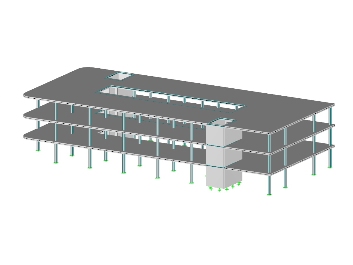
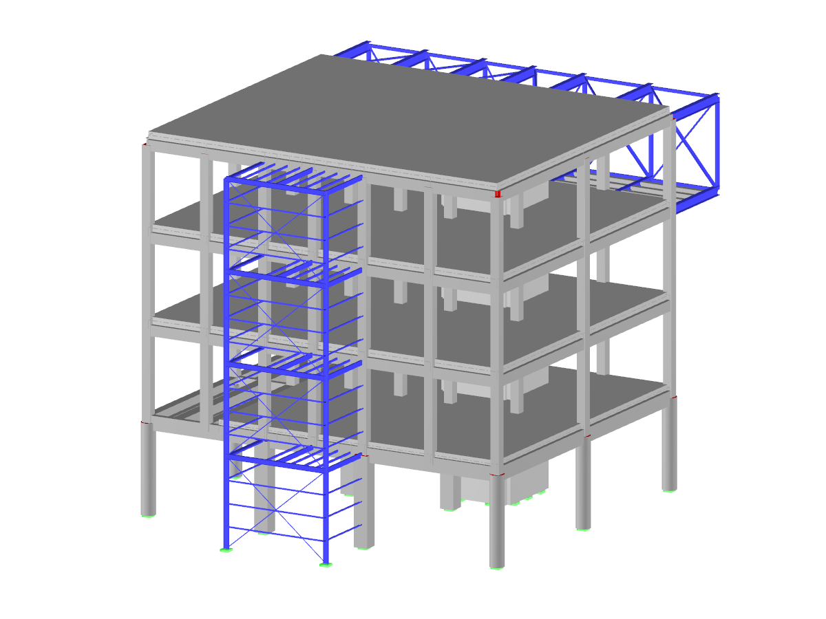
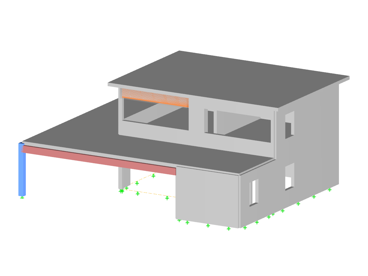
Reinforced Concrete Building
Number of Nodes | 53 |
Number of Lines | 46 |
Number of Members | 11 |
Number of Surfaces | 9 |
Number of Solids | 0 |
Number of Load Cases | 4 |
Number of Load Combinations | 28 |
Number of Result Combinations | 3 |
Total Weight | 256.800 tons |
Dimensions | 52.49 x 10.66 x 39.37 feet |
You can download this structural model to use it for training purposes or for your projects. However, we do not assume any guarantee or liability for the accuracy or completeness of the model.
Do you have individual column sections and angled wall geometries, and need punching shear design for them?
No problem. In RFEM 6, you can perform punching shear design not only for rectangular and circular sections, but for any cross-section shape.
The building model is calculated in two phases:
- Global 3D calculation of the global model, where the slabs are modeled as a rigid plane (diaphragm) or as a bending plate
- Local 2D calculation of the individual floors
After the calculation, the results of the columns and walls from the 3D calculation and the results of the slabs from the 2D calculation are combined in a single model. This means that there is no need to switch between the 3D model and the individual 2D models of the slabs. The user only works with one model, saves valuable time, and avoids possible errors in the manual data exchange between the 3D model and the individual 2D ceiling models.
The vertical surfaces in the model can be divided into shear walls and opening lintels. The program automatically generates internal result members from these wall objects, so they can be designed as members according to any standard in the Concrete Design add-on.
For a response spectrum analysis of building models, you can display the sensitivity coefficients for the horizontal directions by story.
These key figures allow you to interpret the sensitivity to stability effects.
The modal relevance factor (MRF) can help you to assess to which extent specific elements participate in a specific mode shape. The calculation is based on the relative elastic deformation energy of each individual member.
The MRF can be used to distinguish between local and global mode shapes. If multiple individual members show significant MRF (for example, > 20%), the instability of the entire structure or a substructure is very likely. On the other hand, if the sum of all MRFs for an eigenmode is around 100%, a local stability phenomenon (for example, buckling of a single bar) can be expected.
Furthermore, the MRF can be used to determine critical loads and equivalent buckling lengths of certain members (for example, for stability design). Mode shapes for which a specific member has small MRF values (for example, < 20%) can be neglected in this context.
The MRF is displayed by mode shape in the result table under Stability Analysis → Results by Members → Effective Lengths and Critical Loads.