_LI.jpg?mw=960&hash=215861da70692982c3fba53f9cae1dab233ad874)
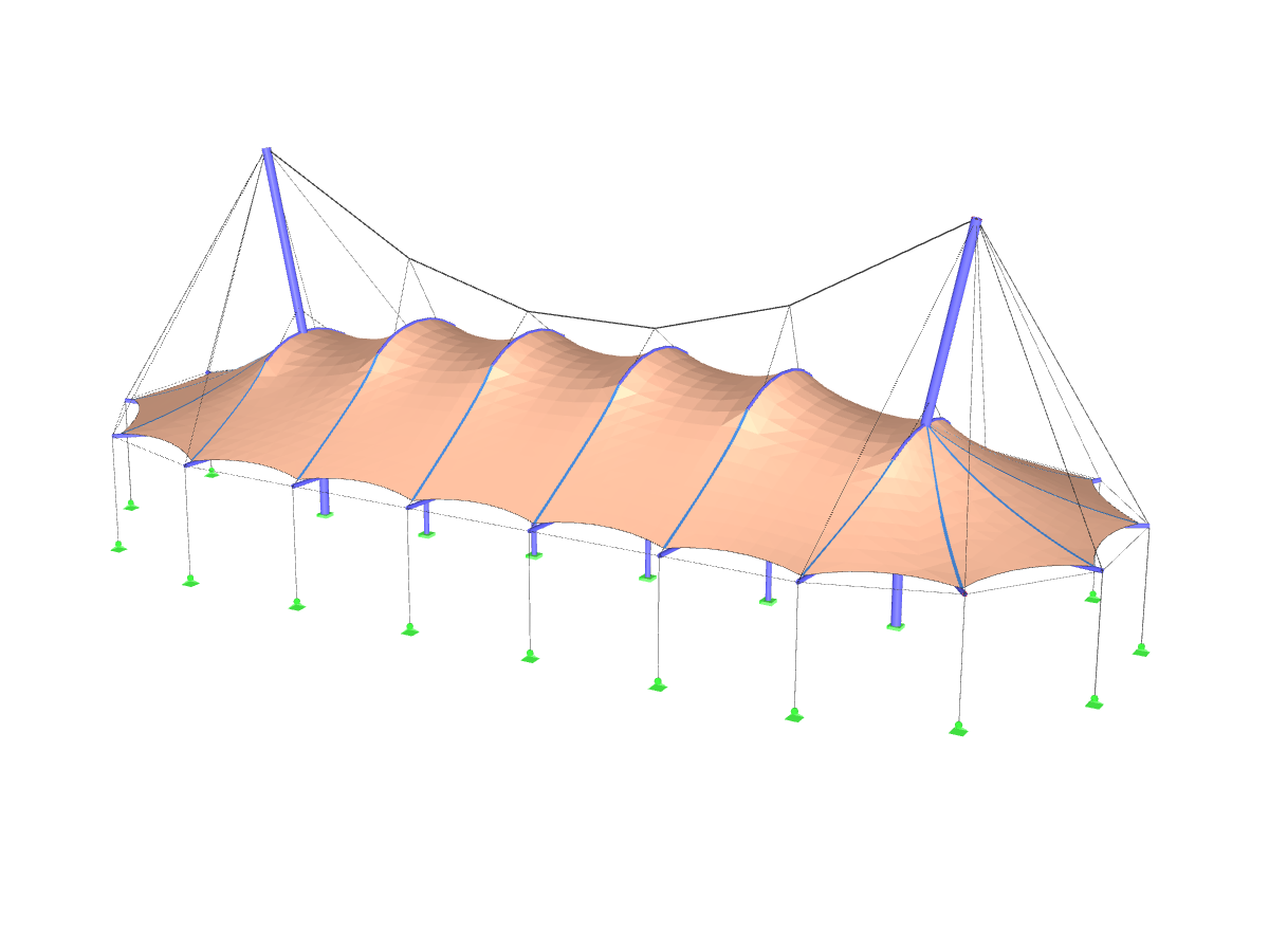
The model describes the membrane roofing of a grandstand, which was completed in time for the 2019 summer season in Dresden. Developed by 3dtex and architect Robert Kerbl – who had already realized the first design 20 years ago – the structure was significantly enlarged due to an increase in the number of visitors. The structural analysis was carried out by zapf & co. using RSTAB, which ensured an optimal design of the roof structure. The light-flooded, tensioned membrane structure impresses with its elegant geometry and the successful integration of functional requirements with visual sophistication.
Model Used in
Extended Grandstand Roofing
No Download Possible
Customer Project / View Only
| Number of Nodes | 6182 |
| Number of Members | 10129 |
| Number of Load Cases | 15 |
| Total Weight | 13.076 t |
| Dimensions (Metric) | 48.122 x 13.349 x 6.381 m |
| Dimensions (Imperial) | 157.88 x 43.8 x 20.94 feet |
| Program Version | 8.21.02 |
Related Models