In Roost, Luxembourg, a new building complex is being built that relates to cars. There will be up to six car dealerships, a parking garage, and a paint shop built on the site. The construction project was divided into two planning phases. The first phase includes three multi-story car dealerships. They have the same supporting structure.
Schatz Engineering, a customer of Dlubal Software, was responsible for the structural and design engineering of the building complex. RSTAB was used for structural design, and Tekla Structures for design engineering.
Structural Analysis and Construction
SCHATZ Engineering GmbH & Co. KGKarlsdorf-Neuthard, Germany
www.toy-engineering.eu
Project Management Realization
Immobilière Industrielle SA/AG
www.rii-sa.lu
Investor
Jos Petry
124 R. Ste Anne
L-5471 Wellenstein, Luxembourg
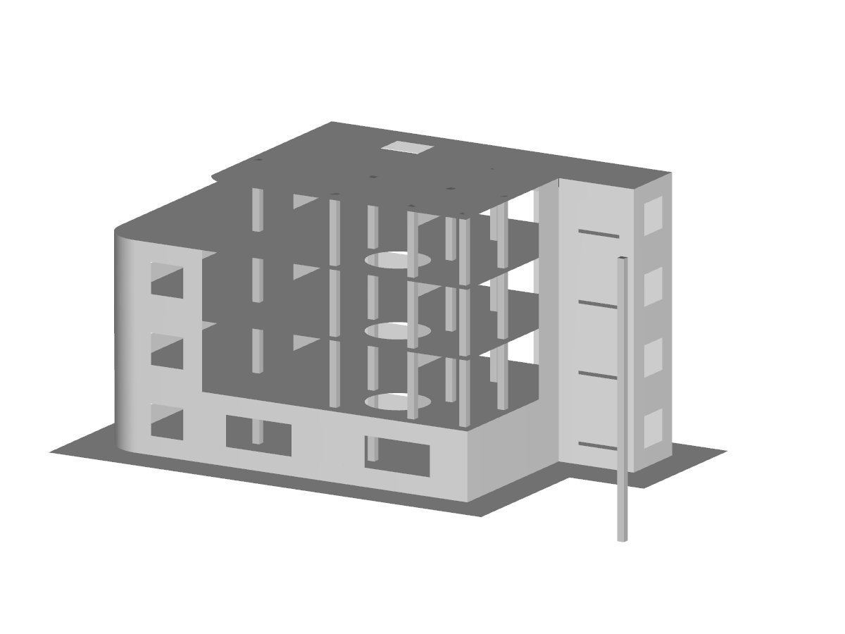
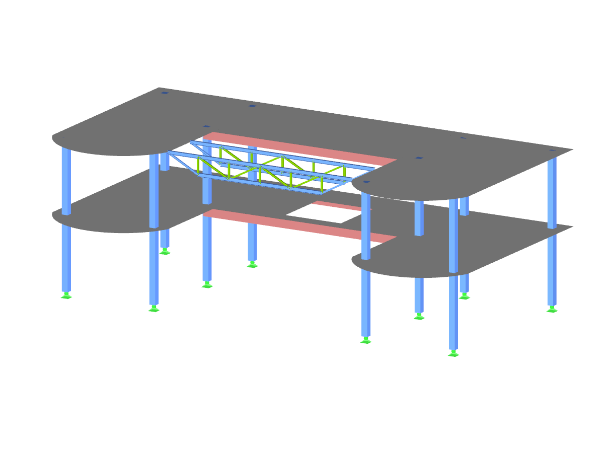
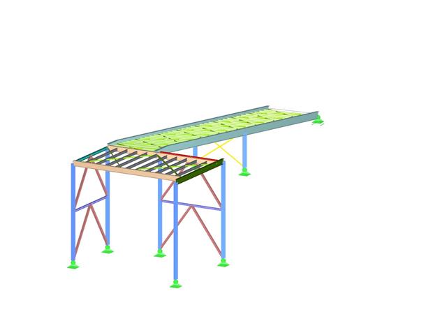
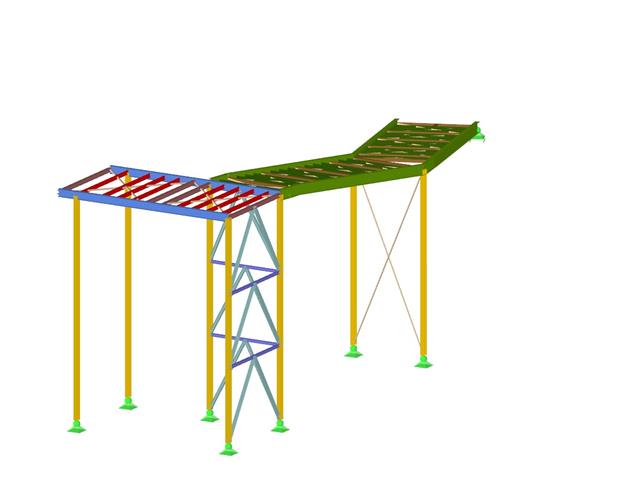
3D Model (© SCHATZ Engineering)
Reinforced Concrete Building
Number of Nodes | 245 |
Number of Members | 420 |
Number of Load Cases | 8 |
Number of Load Combinations | 448 |
Number of Result Combinations | 6 |
Total Weight | 1247.409 tons |
Dimensions | 118.86 x 89.4 x 43.14 feet |
Program Version | 8.09.01 |
In the "Edit Section" dialog box, you can display the buckling shapes of the Finite Strip Method (FSM) as a 3D graphic.
Do you have individual column sections and angled wall geometries, and need punching shear design for them?
No problem. In RFEM 6, you can perform punching shear design not only for rectangular and circular sections, but for any cross-section shape.
- Design of five types of seismic force-resisting systems (SFRS) includes Special Moment Frame (SMF), Intermediate Moment Frame (IMF), Ordinary Moment Frame (OMF), Ordinary Concentrically Braced Frame (OCBF), and Special Concentrically Braced Frame (SCBF)
- Ductility check of the width-to thickness ratios for webs and flanges
- Calculation of the required strength and stiffness for stability bracing of beams
- Calculation of the maximum spacing for stability bracing of beams
- Calculation of the required strength at hinge locations for stability bracing of beams
- Calculation of the column required strength with the option to neglect all bending moments, shear, and torsion for overstrength limit state
- Design check of column and brace slenderness ratios
The seismic design result is categorized into two sections: member requirements and connection requirements.
The "Seismic Requirements" include the Required Flexural Strength and the Required Shear Strength of the beam-to-column connection for moment frames. They are listed in the ‘Moment Frame Connection by Member’ tab. For braced frames, the Required Connection Tensile Strength and the Required Connection Compressive Strength of the brace are listed in the ‘Brace Connection by Member’ tab.
The program provides the performed design checks in tables. The design check details clearly display the formulas and references to the standard.