


Description
In the current validation example, we investigate wind pressure value for both general structural design (Cp,10) and cladding or façade design (Cp,1) of EN 1991-1-4 rectangular plan buildings. [1]. There are three-dimensional cases that we will explain more about them in the next part.
Finding the most accurate and compatible configurations regarding input data, such as turbulence models, wind velocity profiles, turbulence intensities, boundary layer conditions, order of discretization, and other factors, is one of the key aspects of CFD simulation. The important point is the Eurocode does not cover the required information for numerical simulation, such as CFD simulation. We provided here compatible RWIND settings in relation to the example of Eurocode cubic shape. Several formulas and diagrams are used for the static calculation of wind load, which is demonstrated in the following sections.
Analytical Solution and Results
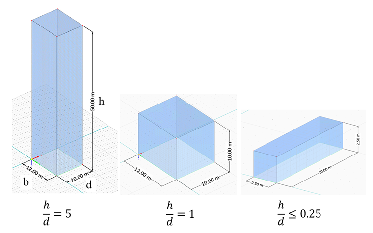
There are three dimensional categories for rectangular cuboid due to the ratio of h/d as shown in figure 1 (EN 1991-1-4 Table 7.1). The input data and assumptions for each dimensional case are illustrated in the next part.
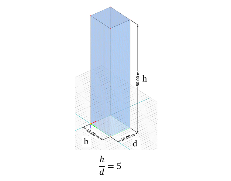
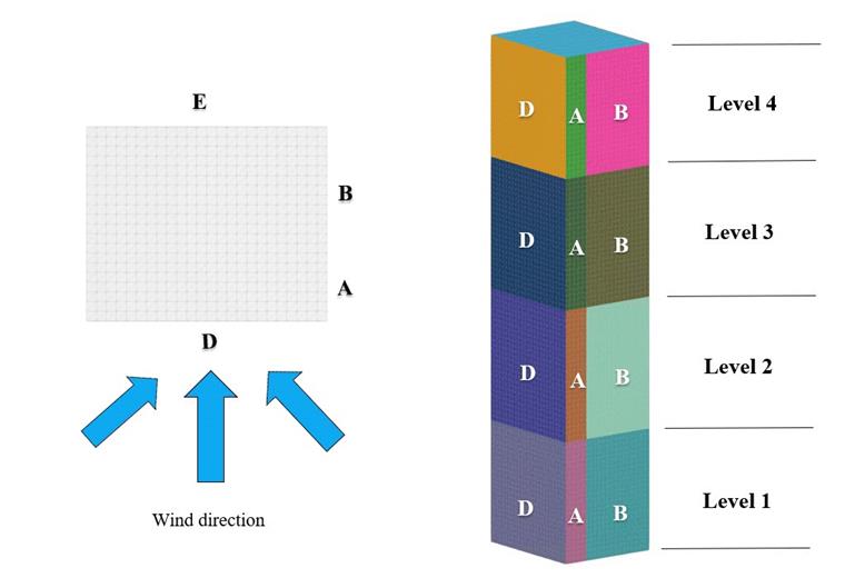
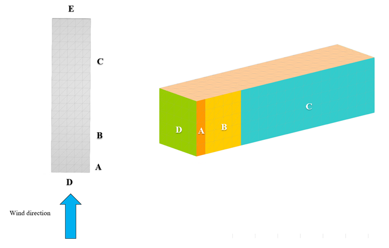
For the first case (figure 2), the high-rise rectangular plan building (h/d=5) is considered regarding the defined zones (figure 3) for each elevation and input data. Also, the terrain category two is considered to create wind velocity and turbulence profile, which is shown in the following table; at the same time, constant values of turbulence intensity are investigated to calculate wind pressure values.
| Table 1: Dimensional Ratio - h/d=5 | |||
| Basic Wind Velocity | V | 30 | m/s |
| Terrain Category | 2 | - | - |
| Height | h | 50 | m |
| Depth | d | 10 | m |
| Width | b | 12 | m |
| Air Density - RWIND | ρ | 1.25 | kg/m3 |
| Turbulence Model - RWIND | Steady RANS k-ω SST | - | - |
| Kinematic Viscosity (Equation 7.15, EN 1991-1-4) - RWIND | ν | 1.5*10-5 | m2/s |
| Scheme Order - RWIND | Second | - | - |
| Residual Target Value - RWIND | 10-5 | - | - |
| Residual Type - RWIND | Pressure | - | - |
| Minimum Number of Iterations - RWIND | 800 | - | - |
| Boundry Layer - RWIND | NL | 10 | - |
| Type of Wall Function - RWIND | Enhanced / Blended | - | - |
| Turbulence Intensity (Best Fit) - RWIND | I | Eurocode Turbulence Profile and 25% | - |
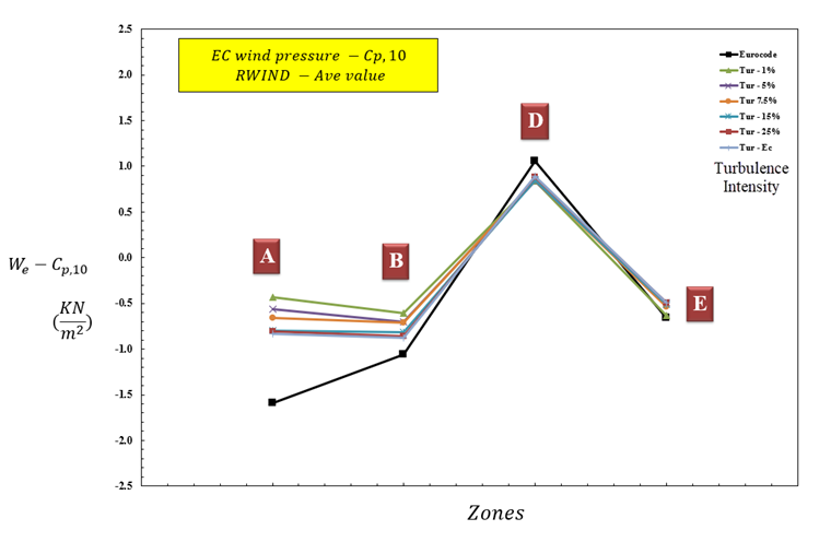
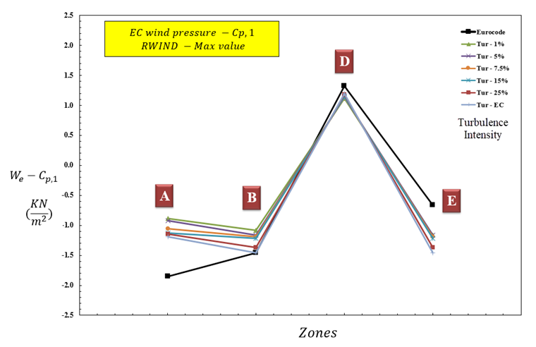
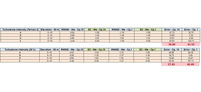
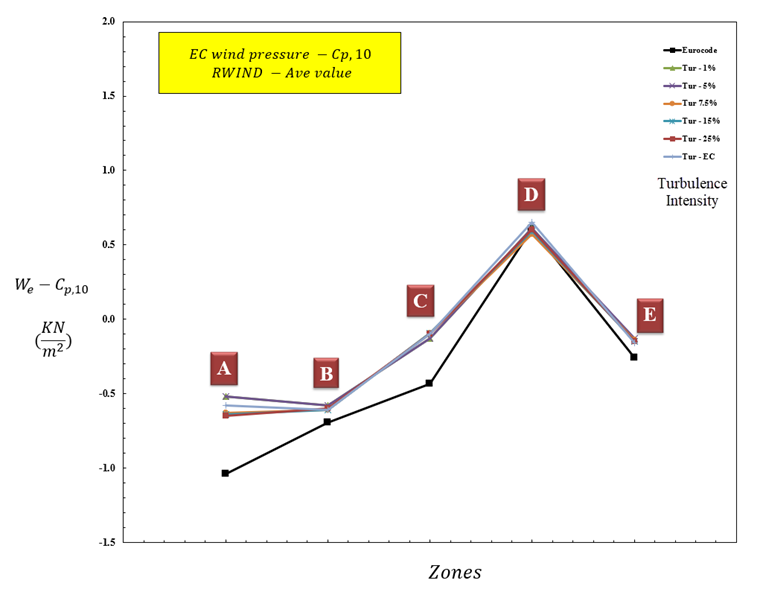
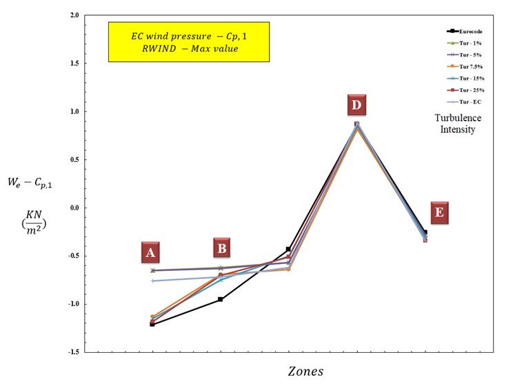
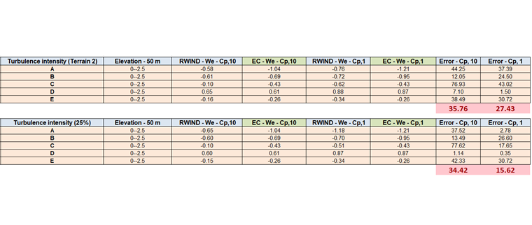
The results of the wind pressure value for Cp,1 and Cp,10 are obtained regarding different zones, dimensional ratios, and turbulence intensities. For the first case, which is high rise cube shape (h/d=5), the results are shown in figure 4 and 5. The results show that there is a good agreement when the real or high turbulence profile (such as 25%) is considered.
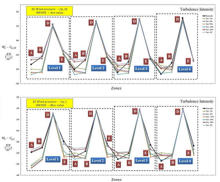
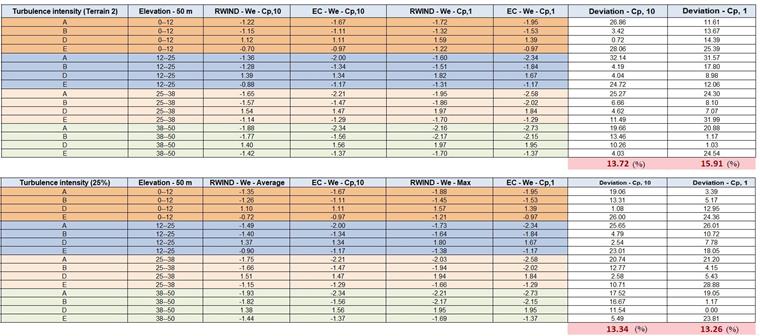
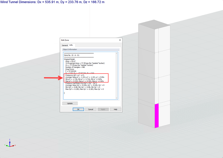
For each zone, it is possible to obtain a maximum pressure value which can be equivalented wind pressure value using Cp,1 for cladding or façade design, and an average pressure value which can be equivalented wind pressure value using Cp,10 for general structural design (figure 6).
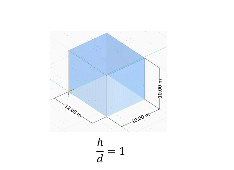
For the next case, middle-rise rectangular plan building (h/d=1) is considered regarding the input data and defined zones (figure 7 and 8), which are shown in the following picture and table:

| Table 2: Dimensional Ratio - h/d=1 | |||
| Basic Wind Speed | V | 30 | m/s |
| Terrain Category | 2 | - | - |
| Height | h | 10 | m |
| Depth | d | 10 | m |
| Width | b | 12 | m |
| Air Density - RWIND | ρ | 1.25 | kg/m3 |
| Turbulence Model - RWIND | Steady RANS k-ω SST | - | - |
| Kinematic Viscosity (Equation 7.15, EN 1991-1-4) - RWIND | ν | 1.5*10-5 | m2/s |
| Scheme Order - RWIND | Second | - | - |
| Residual Target Value - RWIND | 10-5 | - | - |
| Residual Type - RWIND | Pressure | - | - |
| Minimum Number of Iterations - RWIND | 800 | - | - |
| Boundry Layer - RWIND | NL | 10 | - |
| Type of Wall Function - RWIND | Enhanced / Blended | - | - |
| Turbulence Intensity (Best Fit) - RWIND | I | Eurocode Turbulence Profile and 25% - RWIND | - |
For the second case, which is the middle rise cube shape (h/d=1), the value of Cp,10 and Cp,1 are demonstrated in the figure 9, 10. The results show that there is a good agreement when the real as well as high turbulence profile (such as 25%) is considered.
For the last case, short-rise rectangular plan building is considered (h/d=0.25) regarding the input data and defined zones (figure 11 to 13), which are shown in the following pictures and table:
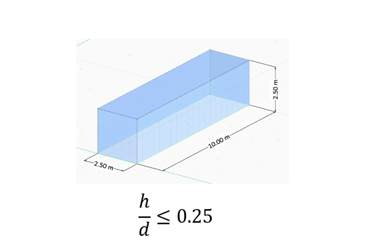
| Table 3: Dimensional Ratio - h/d=0.25 | |||
| Basic Wind Velocity | V | 30 | m/s |
| Terrain Category | 2 | - | - |
| Height | h | 2.50 | m |
| Depth | d | 10 | m |
| Width | b | 2.50 | m |
| Air Density - RWIND | ρ | 1.25 | kg/m3 |
| Turbulence Model - RWIND | Steady RANS k-ω SST | - | - |
| Kinematic Viscosity (Equation 7.15, EN 1991-1-4) - RWIND | ν | 1.5*10-5 | m2/s |
| Scheme Order - RWIND | Second | - | - |
| Residual Target Value - RWIND | 10-5 | - | - |
| Residual Type - RWIND | Pressure | - | - |
| Minimum Number of Iterations - RWIND | 800 | - | - |
| Boundry Layer - RWIND | NL | 10 | - |
| Type of Wall Function - RWIND | Enhanced / Blended | - | - |
| Eurocode Turbulence Profile and 25% - RWIND | I | 15% | - |
For the last case, which is a low-rise rectangular plan building (h/d=0.25), the value of Cp,1 and Cp,10 are shown in the figure 14 to 16. The results show that there is the good agreement when the real or high turbulence profile (such as 25%) is considered.
Conclusion
The results show a good agreement for both general structural designs (Cp10) and cladding or façade design (Cp1) of rectangular plan buildings. Based on the results, generally, the recommended value of turbulence intensity is better to consider as a real Eurocode turbulence profile or choosing higher values (such as I=25%) for different zones and dimensional ratios. It can be seen by increasing the height of the rectangular cuboid and Reynolds numbers of the flow, the results would be more accurate. So specially for high-rise structures, we can expect very good predictions for wind pressure calculation for general structural and façade design.
Also, the rectangular cuboid model with recommended settings is available to download here:
