


Description
In the current validation example, we investigate wind pressure coefficient value (Cp) for both general structural design (Cp,10) and cladding or façade design (Cp,1) based on EN 1991-1-4 flat roof [1] and Japanese Wind Tunnel Data Base. The recommended setting for a three-dimensional flat roof with sharp eaves will be described in the next part.
The key factor of CFD simulation is finding the most compatible configurations with standards regarding input data, such as turbulence models, wind velocity profiles, turbulence intensities, boundary layer conditions, order of discretization, and other factors. The important point is that the standards do not cover the required information for numerical simulation, such as CFD simulation. In the current VE, we presented the most compatible RWIND settings concerning the example of the EN 1991-1-4 sharp edge roof and experimental data from Japanese Wind Tunnel Data Base.
Analytical Solution and Results
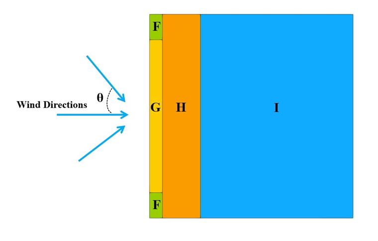
The enclosed sharp eaves model is assumed according to Figure 1, which has four zones (F, G, H, I). The external pressure coefficients (Cp,10) and (Cp,1) for flat roofs are presented in Figure 7.6 and Table 7.2 in EN 1991-1-4. The important assumptions and input data for RWIND that is used for numerical CFD simulation are also shown in Table 1.
| Table 1: Dimensional Ratio and Input Data | |||
| Basic Wind Velocity | V | 22 | m/s |
| Terrain Category | 2 | - | - |
| Crosswind Dimension | b | 16 | m |
| Alongwind Dimension | d | 16 | m |
| Mean Roof Height | h | 4 | m |
| Roof Angle | θroof | 0 | Degree |
| Air Density - RWIND | ρ | 1.25 | kg/m3 |
| Wind Directions | θwind | 0,15, 30, 45 | Degree |
| Turbulence Model - RWIND | Steady RANS k-ω SST | - | - |
| Kinematic Viscosity (Equation 7.15, EN 1991-1-4) - RWIND | ν | 1.5*10-5 | m2/s |
| Scheme Order - RWIND | Second | - | - |
| Residual Target Value - RWIND | 10-4 | - | - |
| Residual Type - RWIND | Pressure | - | - |
| Minimum Number of Iterations - RWIND | 800 | - | - |
| Boundary Layer - RWIND | NL | 10 | - |
| Type of Wall Function - RWIND | Enhanced / Blended | - | - |
| Turbulence Intensity (Best Fit) - RWIND | I | Terrain 2 | - |
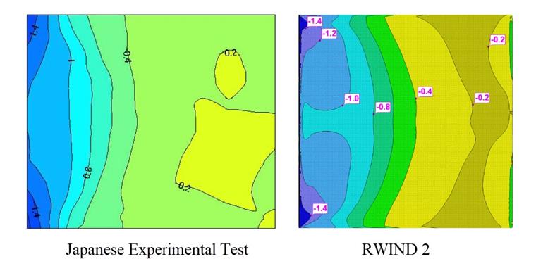
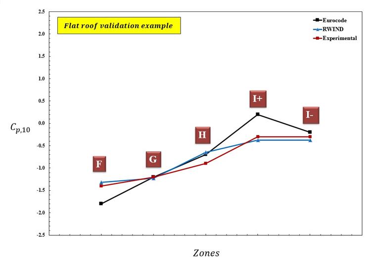
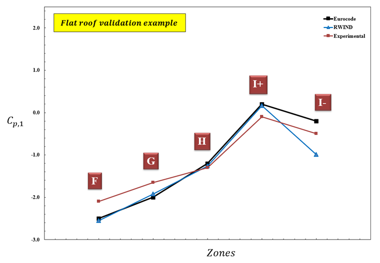
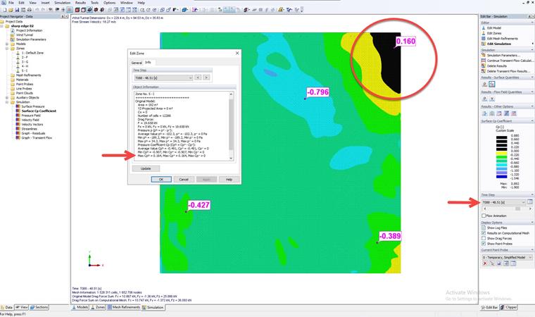
The average wind pressure coefficient (Cp,10) and (Cp,1) is calculated for all zones considering variant wind velocity and turbulence intensities based on terrain 2 category. Four wind directions (θ = 0, 15, 30, 45 degrees) are considered to calculate the corresponding values of (Cp,10) and (Cp,1) related to the Eurocode. The Cp,10 contour is illustrated in Figure 2, which is compared between experimental data from the Japanisch wind tunnel test and RWIND 2. The Cp,10, and Cp,1 values of experimental data, Eurocode, and RWIND are compared in Figure 3 and Figure 4 for a sharp edge. The experimental values are obtained manually by observation of the Cp contour graph in the Japanese database. Also, the wind velocity and turbulence profile in RWIND is set with the EU terrain two formula, which is variant in height. In Figure 5, it can be seen positive Cp,1 on the roof in transient simulation, which is not possible to see in steady simulation. Actually, the effect of wind load fluctuating and vortex shedding can be a better catch in the transient simulation. The critical case through wind direction for constants and variable (based on terrain 2) turbulence intensity are considered for performing wind simulations. The results show a good agreement for most areas when the turbulence profile is close to the Terrain 2 category values. There is a region called (I) in which positive and negative wind pressure coefficients should be considered.
Conclusion
In the current VE example, we investigated the validation of the average Cp value for both Cp,10 and Cp,1 regarding the roof with a sharp edge, which was presented based on EN 1991-1-4 and Japanese wind tunnel data compared to RWIND 2. The results show that the recommended RWIND configuration has good agreement with most zones in Eurocode. The higher turbulence intensity close to the variant turbulence profile of Terrain 2 shows more accurate results than the low turbulence profile. It is important to consider the critical wind direction scenario and transient simulation to obtain an extreme value of EN 1991-1-4. The deviation values mostly came from safety factors and the statistical approach, which presents a conservative approach that is used in the standard.
Also, the flat roof model with recommended settings is available to download here: