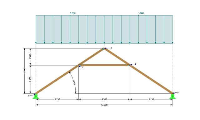
A collar beam roof with the selected geometry is compared in terms of its internal forces between the calculation using RFEM 6 and the manual calculation. In total, three load systems are analyzed.

This example compares the effective lengths and critical load factor, which can be calculated in RFEM 6 using the Structure Stability add-on, with a manual calculation. The structural system is a rigid frame with two additional hinged columns. This column is loaded by vertical concentrated loads.

In this example, the shear at the interface between concrete cast at different times and the corresponding reinforcement are determined according to DIN EN 1992-1-1. The obtained results with RFEM 6 will be compared to the hand calculation below.
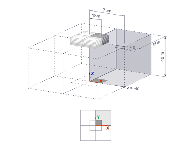
The settlements of a rigid square foundation on a lacustrine clay [1] are calculated with RFEM. One quarter of the foundation is modelled. The foundation has a width of 75.0 m in both sides. Construction stages are used to generate the results.
Verify that a beam of different cross-sections made of Alloy 6061-T6 is adequate for the required load, in accordance with the 2020 Aluminum Design Manual.
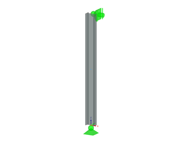
Determine the allowable axial compressive strength of a pinned 8-foot-long beam of various cross-sections made of Alloy 6061-T6 and laterally restrained to prevent buckling about its weak axis in accordance with the 2020 Aluminum Design Manual.
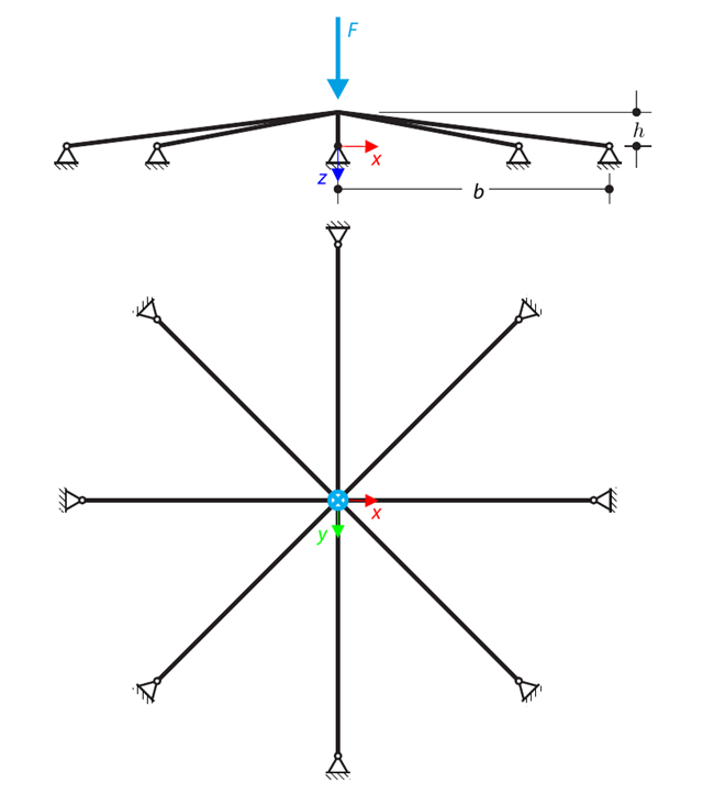
A symmetrical shallow structure is made of eight equal truss members, which are embedded into hinge supports. The structure is loaded by a concentrated force and alternatively by imposed nodal deformation over the critical limit point when the snap-through occurs. Imposed nodal deformation is used in RFEM 5 and RSTAB 8 to obtain the full equilibrium path of the snap-through. The self-weight is neglected in this example. Determine the relationship between the actual loading force and the deflection, considering large deformation analysis. Evaluate the load factor at the given deflections.
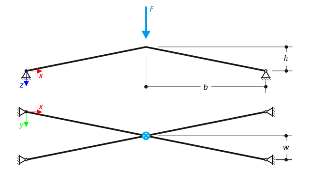
A structure is made of four truss members, which are embedded into hinge supports. The structure is loaded by a concentrated force and alternatively by imposed nodal deformation over the critical limit point, when snap-through occurs. Imposed nodal deformation is used in RFEM 5 and RSTAB 8 to obtain the full equilibrium path of the snap-through. The self-weight is neglected in this example. Determine the relationship between the actual loading force and the deflection, considering large deformation analysis. Evaluate the load factor at given deflections.
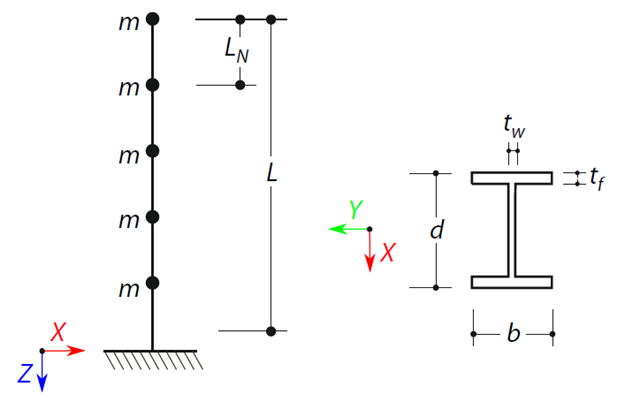
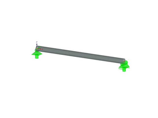
A cantilever beam with an I-beam cross-section of length L is defined. The beam has five mass points with masses m acting in the X-direction. The self-weight is neglected. The frequencies, mode shapes, and equivalent loads of this 5-DOF system are analytically calculated and compared with the results from RSTAB and RFEM.
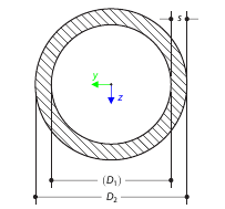
Determine the torsional constant for the cross-section of the tube (annular area) analytically, and compare the results with the numerical solution in RFEM 5 and RSTAB 8 for various wall thicknesses.