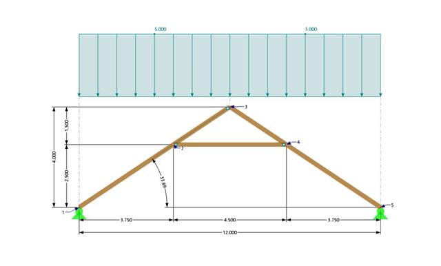
A collar beam roof with the selected geometry is compared in terms of its internal forces between the calculation using RFEM 6 and the manual calculation. In total, three load systems are analyzed.

A reinforced concrete beam is designed as a two-span beam with a cantilever. The cross-section varies along the length of the cantilever (tapered cross-section). The internal forces, the required longitudinal and shear reinforcement for the ultimate limit state are calculated.

The model is based on the example 4 of [1]: Point-supported slab.
The flat slab of an office building with crack-sensitive lightweight walls is to be designed. Inner, border and corner panels are to be investigated. The columns and the flat slab are monolithically joined. The edge and corner columns are placed flush with the edge of the slab. The axes of the columns form a square grid. It is a rigid system (building stiffened with shear walls).
The office building has 5 floors with a floor height of 3.000 m. The environmental conditions to be assumed are defined as "closed interior spaces". There are predominantly static actions.
The focus of this example is to determine the slab moments and the required reinforcement above the columns under full load.
The model is based on the example 4 of [1]: Point-supported slab. The internal forces and the required longitudinal reinforcement can be found the in verification example 1022. In this example, punching is examined in the axis B/2.
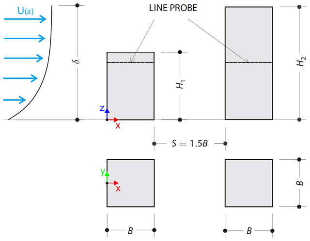
The verification example describes pressure loads on the walls of buildings in tandem arrangement located at ground level. The buildings are simplified to rectangular objects and scaled down while maintaining the elevation ratios. The pressure distribution on the walls of the model of a medium-high building was conducted by an experiment. The chosen results (pressure coefficient Cp) are compared with the measured values.
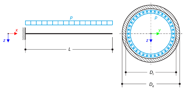
A pipe with a tubular cross-section is loaded by internal pressure. This internal pressure causes axial deformation of the pipe (the Bourdon effect). Determine the axial deformation of the pipe endpoint.
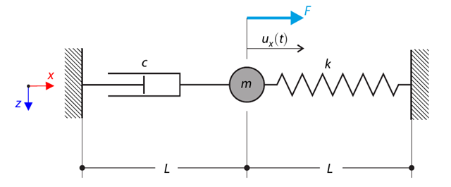
A single-mass system with dashpot is subjected to a constant loading force. Determine the spring force, damping force, and inertial force at the given test time. In this verification example, the Kelvin--Voigt dashpot (namely, a spring and a damper element in serial connection) is decomposed into its purely viscous and purely elastic parts, in order to better evaluate the reaction forces.
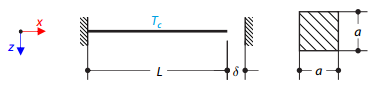
A steel rod between two rigid supports with a gap is loaded by a temperature difference. While neglecting self‑weight, determine the total deformation of the rod and its internal axial force.