Description
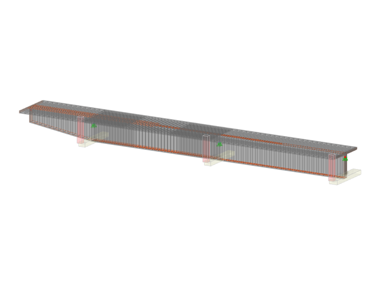
A reinforced concrete beam is designed as a two-span beam with a cantilever. The cross-section varies along the length of the cantilever (tapered cross-section). The internal forces, the required longitudinal and shear reinforcement for the ultimate limit state are calculated and compared to the results in [1].
| Material | Concrete C25/30 | Modulus of Elasticity | E | 31000 | N/mm2 |
| Design value of concrete compressive strength | fcd | 14.167 | N/mm2 | ||
| Reinforcing Steel B500S(B) | Characteristic yield strength | fyk | 500.000 | N/mm2 | |
| Design yield strength | fyd | 434.783 | N/mm2 | ||
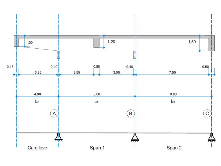
| Geometry | Structure | Cantilever length | leff,cantilever | 4.000 | m |
| Span 1 length | leff,1 | 8.000 | m | ||
| Span 2 length | leff,2 | 8.000 | m | ||
| Cross-section | Height | h | 1500 | mm | |
| Width | b | 2620 | mm | ||
| Flange height | hf | 150 | mm | ||
| Web width | bw | 380 | mm | ||
| Concrete cover | cnom | 35 | mm | ||
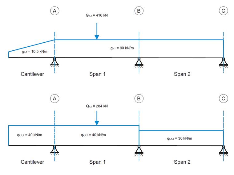
| Loads | Permanant loads | LC1 | gk,1 | 10.500 - 90.000 (trapezoidal) | kN/m |
| LC2 | Gk,2 | 216.000 | kN | ||
| LC3 | Gk,3 | 416.000 | kN | ||
| Imposed loads | LC4 | qk,1,1 | 40.000 | kN/m | |
| LC5 | qk,1,2 | 40.000 | kN/m | ||
| LC6 | qk,1,3 | 30.000 | kN/m | ||
| LC7 | Qk,2 | 284.000 | kN |
RFEM Settings
- Consideration of limited moment redistribution of the supporting moment acc. to 5.5
- Reduction of the moments or dimensioning for the momentsat the face of a monolithic support acc. to 5.3.2.2
- Reduction of shear forces in the support face and distance d acc. to 6.2.1(8)
- The distribution type of the section used is tapered at start of member, to consider the height change of the cross-section.
Results
Bending Moment and Shear force from Permanant and Imposed Loads
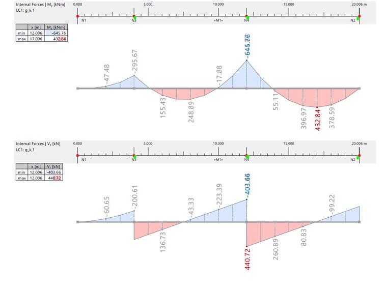
| Bending Moment and Shear Force due to gk,1 | |||||||
| Inner Force | Unit | RFEM / Analytical Solution | Span 1 | Span 2 | Axis A | Axis B | Axis C |
| Bending Moment | [kNm] | RFEM | 248.890 | 432.840 | -296.460 | -645.760 | 0 |
| Analytical Solution | 249.000 | 433.000 | -296.000 | -646.000 | 0 | ||
| Shear Force | [kN] | RFEM | -43.330 | 80.830 | -201.000/316.340 | -403.660/440.720 | -279.280 |
| Analytical Solution | -44.000 | 81.000 | -201.000/316.000 | -404.000/441.000 | -279.000 | ||
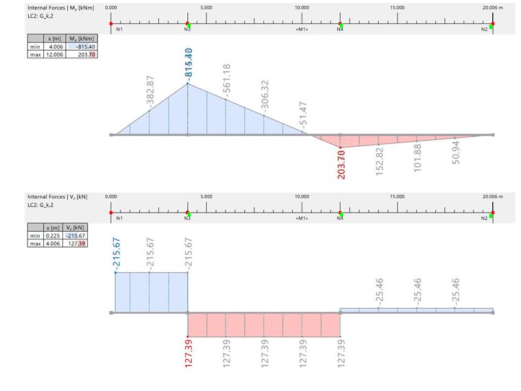
| Bending Moment and Shear Force due to Gk,2 | |||||||
| Inner Force | Unit | RFEM / Analytical Solution | Span 1 | Span 2 | Axis A | Axis B | Axis C |
| Bending Moment | [kNm] | RFEM | -305.850 | 101.850 | -815.400 | 203.720 | 0 |
| Analytical Solution | -306.000 | 102.000 | -815.000 | 204.000 | 0 | ||
| Shear Force | [kN] | RFEM | 127.390 | -25.460 | -215.670/127.390 | -127.390/-25.460 | -25.460 |
| Analytical Solution | 127.000 | -25.500 | -216.000/127.000 | -127.000/-25.500 | -25.500 | ||
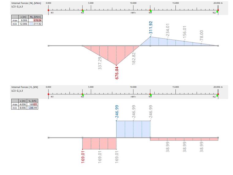
| Bending Moment and Shear Force due to Gk,3 | |||||||
| Inner Force | Unit | RFEM / Analytical Solution | Span 1 | Span 2 | Axis A | Axis B | Axis C |
| Bending Moment | [kNm] | RFEM | 676.040 | -155.960 | 0 | -311.920 | 0 |
| Analytical Solution | 676.000 | 156.000 | 0 | -312.000 | 0 | ||
| Shear Force | [kN] | RFEM | 169.010/-246.990 | -38.990 | 169.010 | -246.990/38.990 | 38.990 |
| Analytical Solution | 169.000/247.000 | 39.000 | 169.000 | -247.000/39.000 | 39.000 | ||
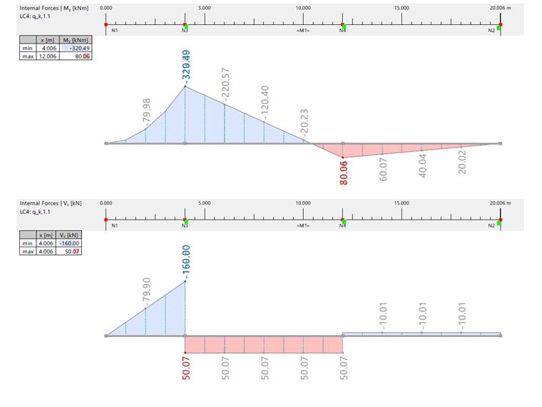
| Bending Moment and Shear Force due to qk,1,1 | |||||||
| Inner Force | Unit | RFEM / Analytical Solution | Span 1 | Span 2 | Axis A | Axis B | Axis C |
| Bending Moment | [kNm] | RFEM | -120.100 | 40.000 | -320.200 | 79.950 | 0 |
| Analytical Solution | -120.220 | 40.030 | -320.490 | 80.060 | 0 | ||
| Shear Force | [kN] | RFEM | 50.070 | -10.000 | -160.000/50.020 | 50.020/-10.000 | -10.000 |
| Analytical Solution | 50.000 | -10.010 | -160.000/50.070 | 50.070/-10.010 | -10.010 | ||
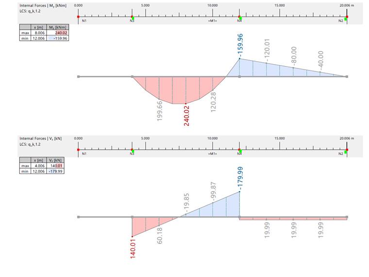
| Bending Moment and Shear Force due to qk,1,2 | |||||||
| Inner Force | Unit | RFEM / Analytical Solution | Span 1 | Span 2 | Axis A | Axis B | Axis C |
| Bending Moment | [kNm] | RFEM | 240.020 | -79.980 | 0 | -159.960 | 0 |
| Analytical Solution | 240.000 | -80.000 | 0 | -160.000 | 0 | ||
| Shear Force | [kN] | RFEM | -19.990 | 19.990 | 140.010 | -179.990/19.999 | 19.999 |
| Analytical Solution | -20.000 | 20.000 | 140.000 | -180.000/20.000 | 20.000 | ||
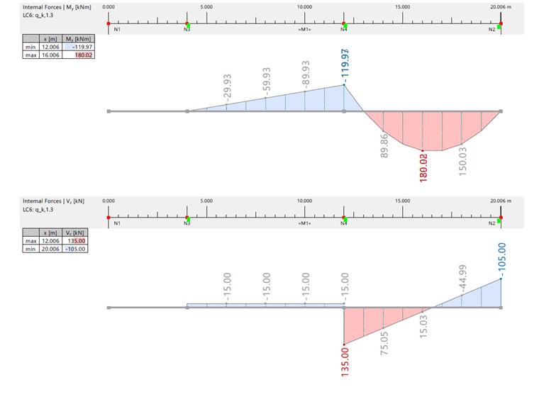
| Bending Moment and Shear Force due to qk,1,3 | |||||||
| Inner Force | Unit | RFEM / Analytical Solution | Span 1 | Span 2 | Axis A | Axis B | Axis C |
| Bending Moment | [kNm] | RFEM | -59.980 | 180.010 | 0 | -119.970 | 0 |
| Analytical Solution | -60.000 | 184.000 | 0 | -120.000 | 0 | ||
| Shear Force | [kN] | RFEM | -15.000 | 15.000 | -15.000 | -15.000/135.000 | -105.000 |
| Analytical Solution | -15.000 | 15.000 | -15.000 | -15.000/135.000 | -105.000 | ||
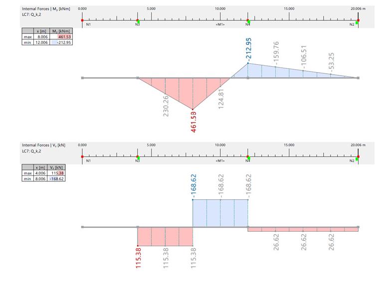
| Bending Moment and Shear Force due to Qk,2 | |||||||
| Inner Force | Unit | RFEM / Analytical Solution | Span 1 | Span 2 | Axis A | Axis B | Axis C |
| Bending Moment | [kNm] | RFEM | 461.530 | -106.470 | 0 | -212.950 | 0 |
| Analytical Solution | 462.000 | -106.500 | 0 | -213.000 | 0 | ||
| Shear Force | [kN] | RFEM | 115.380/-168.620 | 26.620 | 115.380 | -168.620/26.620 | 26.620 |
| Analytical Solution | -169.000/115.000 | 26.600 | 115.000 | -15.000/135.000 | -169.000/26.600 | ||
Internal Forces
The table below contains all the load combinations of the ultimate limit state:
| Load Comibation | Assigned Load Cases |
| CO1 | 1.00·LC1 + 1.00·LC2 + 1.00·LC3 |
| CO2 | 1.35·LC1 + 1.35·LC2 + 1.35·LC3 + 1.50·LC4 + 1.50·LC5 + 1.50·LC6 + (1.50·0.80)·LC7 |
| CO3 | 1.35·LC1 + 1.35·LC2 + 1.35·LC3 + (1.50·0.70)·LC4 + (1.50·0.70)·LC5 + (1.50·0.70)·LC6 + 1.50·LC7 |
| CO4 | 1.35·LC1 + 1.00·LC2 + 1.35·LC3 + 1.50·LC5 + 1.50·LC6 + (1.50·0.80)·LC7 |
| CO5 | 1.35·LC1 + 1.00·LC2 + 1.35·LC3 + (1.50·0.70)·LC5 + 1.50·LC7 |
| CO6 | 1.00·LC1 + 1.35·LC2 + 1.35·LC3 + (1.50·0.70)·LC4 + 1.50·LC7 |
| CO7 | 1.35·LC1 + 1.00·LC2 + 1.35·LC3 + (1.50·0.70)·LC5 + (1.50·0.70)·LC6+ 1.50·LC7 |
| CO8 | 1.35·LC1 + 1.35·LC2 + 1.00·LC3 + 1.50·LC4 + 1.50·LC6 |
| CO9 | 1.35·LC1 + 1.35·LC2 + 1.35·LC3 + 1.50·LC4 + 1.50·LC5 + (1.50·0.80)·LC7 |
| Action | Unit | Load Combination | RFEM Result | Reference Result | Ratio |
| MEd,A | kNm | CO8 | -1981.830 | -1980.000 | 1.00 |
| MEd,B | kNm | CO4 | -1764.600 | -1765.000 | 0.99 |
| MEd,1 | kNm | CO5 | 1887.120 | 1887.000 | 1.00 |
| MEd,2 | kNm | CO8 | 885.540 | 895.000 | 0.99 |
| VEd,A,li | kN | CO2 | -802.500 | -803.000 | 0.99 |
| VEd,A,re | kN | CO9 | 1250.770 | 1250.000 | 1.00 |
| VEd,1,li | kN | CO6 | 582.090 | 581.000 | 1.00 |
| VEd,1,re | kN | CO7 | -554.660 | -555.000 | 0.99 |
| VEd,B,li | kN | CO4 | -1245.820 | -1246.000 | 0.99 |
| VEd,B,re | kN | CO4 | -886.580 | -887.000 | 0.99 |
| VEd,C | kN | CO8 | -544.930 | -545.000 | 0.99 |
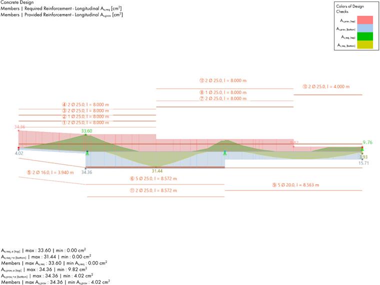
Required Longitudinal Reinforcement
In the literature, a 15% moment redistribution was considered at support B within load combinations 4, and a 12% moment redistribution was considered within load combination 7. In contrast, RFEM applies the same moment redistribution across all load combinations. To facilitate a meaningful comparison with the literature, adjustments will be made to the RFEM model. Subsequently, the actual solution provided by RFEM will be presented.
Comparing RFEM results to literature results:
Support A:
The beam is monolithically connected to the support, and therefore, the critical design moment is at the face of the support. However, the literature neglects the influence of the load when calculating the moment at the face of the support. To enable a meaningful comparison with the results in RFEM, it is necessary to recalculate it while considering the influence of the load. The design moment at the face of the support without load influence consideration, MEd, is -1819.0 kNm. Considering the effect of the loads, MEd increases to -1823.0 kNm.
| RFEM | Analytical Solution | Ratio | ||||
| Load Case | Design Bending Moment MEd | Required Reinforcement As,stat,tot | Design Bending Moment MEd | Required Reinforcement As,stat,tot | MEd | As,stat,tot |
| [kNm] | [cm2] | [kNm] | [cm2] | [kNm] | [cm2] | |
| CO8 | -1824.790 | 32.50 | -1823.000 | 31.60 | 1.00 | 1.02 |
In the literature, it is assumed that the cross-section height at the edge of the support is equal to the cross-section height at the middle of the support. However, in RFEM, the actual cross-section height is considered due to the tapered cross-section. As a result, this leads to higher reinforcement requirements in RFEM.
Support B:
The critical load combination in this case is the load combination 4. To match the literature, the ratio of moment redistribution in the support B is set to 0.850.
| Support B | ||||||
| RFEM | Analytical Solution | Ratio | ||||
| Load Case | Design Bending Moment MEd | Required Reinforcement As,stat,tot | Design Bending Moment MEd | Required Reinforcement As,stat,tot | MEd | As,stat,tot |
| [kNm] | [cm2] | [kNm] | [cm2] | [kNm] | [cm2] | |
| CO4 | -1345.870 | 22.40 | -1360.000 | 22.80 | 0.99 | 0.98 |
When calculating the design moment, the literature takes into consideration that the moment at the face of the support should not be less than 0.65 of the full fixed end moment (DIN EN 1992-1-1, 5.3.2.2). This condition is not implemented in RFEM. This explains the difference in the design moment.
Span 1:
Since the beam is defined as a continuous member in RFEM, it is not possible to set an effective width beff to each span. The smallest value from the two effective widths from span 1 and 2 is used for simplification. beff is than set to 2.620 m. The literature considers a 12% moment redistrubiton for the load combination 7, the moment redistribution ratio in the middle support is therefore now set to 0.880.
| Span 1 | ||||||
| RFEM | Analytical Solution | Ratio | ||||
| Load Case | Design Bending Moment MEd | Required Reinforcement As,stat,tot | Design Bending Moment MEd | Required Reinforcement As,stat,tot | MEd | As,stat,tot |
| [kNm] | [cm2] | [kNm] | [cm2] | [kNm] | [cm2] | |
| CO7 | 1926.280 | 30.13 | 1927.000 | 33.10 | 0.99 | 0.91 |
Span 2:
In this case, no moment redistribution is considered. The ratio of moment redistribution is set to 1.000.
| Span 2 | ||||||
| RFEM | Analytical Solution | Ratio | ||||
| Load Case | Design Bending Moment MEd | Required Reinforcement As,stat,tot | Design Bending Moment MEd | Required Reinforcement As,stat,tot | MEd | As,stat,tot |
| [kNm] | [cm2] | [kNm] | [cm2] | [kNm] | [cm2] | |
| CO8 | 885.520 | 13.79 | 895.000 | 15.10 | 0.99 | 0.91 |
In the literature, the required longitudinal reinforcement is determined using approximation methods for T-beams according to DAstb-heft 425. Using this method, the compressive force in the flange is assumed to be in the center of the flange (hf/2). in RFEM, the required reinforcement is determined with a cross-section analysis. This results in a required reinforcement lower than in the literature.
RFEM provided solution
Now, the moment redistribution in the middle support is set to 15% across all load combinations. The results are summarized in the tables below.
Support A:
Load case 8 delivers the highest bending moment, and is therefore decisive.
| Support A | ||
| Load Case | Design Bending Moment MEd | Required Reinforcement As,stat,tot |
| [kNm] | [cm2] | |
| CO8 | -1824.840 | 32.32 |
Support B:
| Support B: | ||
| Load Case | Design Bending Moment MEd | Required Reinforcement As,stat,tot |
| [kNm] | [cm2] | |
| CO4 | -1345.890 | 22.40 |
Span 1:
When moment redistribution is taken into consideration in all load combinations, CO5 has the highest design bending moment in Span 1.
| Span 1: | ||
| Load Case | Design Bending Moment MEd | Required Reinforcement As,stat,tot |
| [kNm] | [cm2] | |
| CO5 | 2005.410 | 31.44 |
Span 2:
CO8 has a design moment after moment redistibution MEd of 940 kNm.
| Span 2: | ||
| Load Case | Design Bending Moment MEd | Required Reinforcement As,stat,tot |
| [kNm] | [cm2] | |
| CO8 | 940.000 | 14.73 |
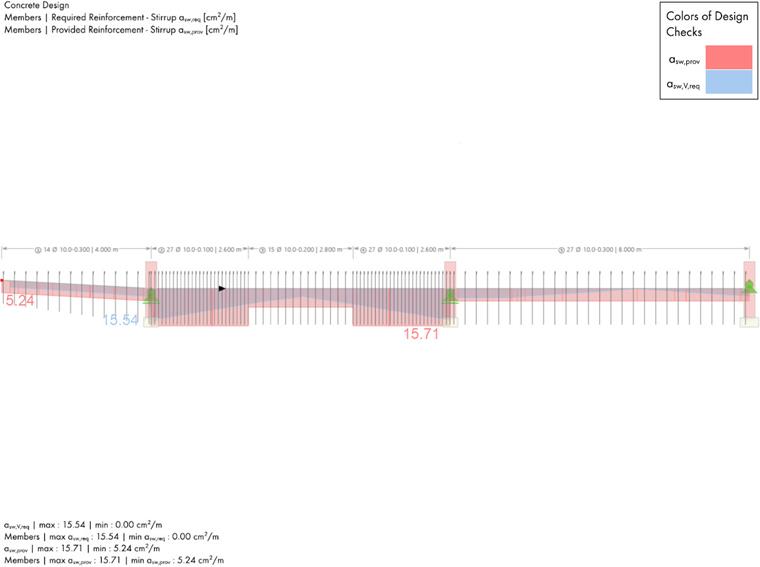
Shear Reinforcement
Shear reinforcement in the cantilever:
To determine the required stirrups in the cantilever, 3 locations are examined. The results are summarized in the table below:
| Cantilever | ||||||
| Location x | Parameter | Symbol | Unit | RFEM | Analytical Solution | Ratio |
| x = 0.45m | Effective depth | d | [m] | 0.940 | 0.920 | 1.02 |
| Inner lever arm | z | [m] | 0.848 | 0.828 | 1.02 | |
| Shear force | VEd | [kN] | -327.190 | -328.000 | 0.99 | |
| Design bending moment | MEd | [kNm] | -73.320 | -74.000 | 0.99 | |
| Design shear component of the force in compression area | Vccd | [kN] | 12.550 | 13.000 | 0.99 | |
| Design shear force | VEd,red | [kN] | 314.640 | 314.000 | 1.0 | |
| Shear capacity without reinforcement | Vrd,cc | [kN] | 219.420 | 221.00 | 0.99 | |
| Inclination of the compression strut | cot Θ | [-] | 3.0 | 3.0 | 1.0 | |
| Capacity of compression strut | Vrd,max | [kN] | 996.230 | 1003.000 | 0.99 | |
| Required reinforcement | asw,req | [cm2/m] | 2.84 | 2.91 | 0.98 | |
| x = 1.37m | Effective depth | d | [m] | 1.070 | 1.050 | 1.02 |
| Inner lever arm | z | [m] | 0.965 | 0.945 | 1.02 | |
| Shear force | VEd | [kN] | -417.720 | -418.000 | 1.00 | |
| Design bending moment | MEd | [kNm] | -414.250 | -415.000 | 1.00 | |
| Design shear component of the force in compression area | Vccd | [kN] | 62.210 | 66.000 | 0.94 | |
| Design shear force | VEd,red | [kN] | 355.510 | 353.000 | 1.01 | |
| Shear capacity without reinforcement | Vrd,cc | [kN] | 250.070 | 252.000 | 0.99 | |
| Inclination of the compression strut | cot Θ | [-] | 3.0 | 3.0 | 1.0 | |
| Capacity of compression strut | Vrd,max | [kN] | 1135.860 | 1144.000 | 0.99 | |
| Required reinforcement | asw,req | [cm2/m] | 2.83 | 2.86 | 0.99 | |
| x = 2.37m | Effective depth | d | [m] | 1.210 | 1.190 | 1.02 |
| Inner lever arm | z | [m] | 1.090 | 1.070 | 1.02 | |
| Shear force | VEd | [kN] | -541.800 | -543.000 | 1.0 | |
| Design bending moment | MEd | [kNm] | -891.790 | -893.00 | 1.00 | |
| Design shear component of the force in compression area | Vccd | [kN] | 118.250 | 125.000 | 0.95 | |
| Design shear force | VEd,red | [kN] | 423.550 | 418.000 | 1.01 | |
| Shear capacity without reinforcement | Vrd,cc | [kN] | 283.220 | 285.000 | 0.99 | |
| Inclination of the compression strut | cot Θ | [-] | 3.0 | 3.0 | 1.0 | |
| Capacity of compression strut | Vrd,max | [kN] | 1286.410 | 1298.000 | 0.99 | |
| Required reinforcement | asw,req | [cm2/m] | 2.98 | 2.99 | 1.0 | |
The decisive member location for the calculation of the stirrups in field 1 is at a distance d from the right edge of the support A.
| Span 1 | |||||
| Parameter | Symbol | Unit | RFEM | Analytical Solution | Ratio |
| Effective depth | d | [m] | 1.440 | 1.430 | 1.00 |
| Shear force at the support A | VEd,A | [kN] | 1250.770 | 1250.000 | 1.00 |
| Design shear force | VEd,A,re | [kN] | 952.430 | 954.000 | 1.00 |
| Shear capacity without reinforcement | VRd,cc | [kN] | 346.210 | 343.000 | 1.00 |
| Inclination of compression strut | cot Θ | [-] | 1.88 | 1.87 | 1.00 |
| Required shear reinforcment | asw,req | [cm2/m] | 8.95 | 9.11 | 0.98 |
The calculation of the stirrups is done analog to span 1.
| Span 2 | |||||
| Parameter | Symbol | Unit | RFEM | Analytical Solution | Ratio |
| Effective depth | d | [m] | 1.440 | 1.440 | 1.02 |
| Shear force at the support B | VEd,B | [kN] | 886.580 | 855.000 | 1.03 |
| Design shear force | VEd,B,re | [kN] | 613.100 | 584.000 | 1.05 |
| Shear capacity without reinforcement | VRd,cc | [kN] | 346.210 | 343.000 | 1.00 |
| Inclination of compression strut | cot Θ | [-] | 2.75 | 2.91 | 0.95 |
| Required shear reinforcment | asw,req | [cm2/m] | 3.94 | 3.58 | 1.10 |
The differences in the results for span 2 are due to the fact that the literature considered the shear force at support B after moment redistribution. However, moment redistribution does not influence the shear force design in RFEM.