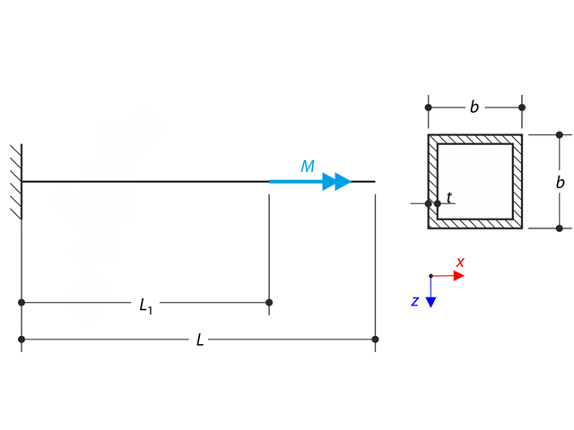
A thin-walled cantilever of a QRO-profile is fully fixed on the left end and warping is free. The cantilever is subjected to torque. Small deformations are considered, and the self-weight is neglected. Determine the maximum rotation, primary moment, secondary moment, and warping moment. The verification example is based on the example introduced by Gensichen and Lumpe.

In the current validation example, we investigate wind pressure coefficient (Cp) of flat roof and walls with ASCE7-22 [1]. In the section 28.3 (Wind loads - main wind force resisting system) and Figure 28.3-1 (load case 1), there is a table which shows Cp value for different roof angle.

The model is based on the example 4 of [1]: Point-supported slab.
The flat slab of an office building with crack-sensitive lightweight walls is to be designed. Inner, border and corner panels are to be investigated. The columns and the flat slab are monolithically joined. The edge and corner columns are placed flush with the edge of the slab. The axes of the columns form a square grid. It is a rigid system (building stiffened with shear walls).
The office building has 5 floors with a floor height of 3.000 m. The environmental conditions to be assumed are defined as "closed interior spaces". There are predominantly static actions.
The focus of this example is to determine the slab moments and the required reinforcement above the columns under full load.
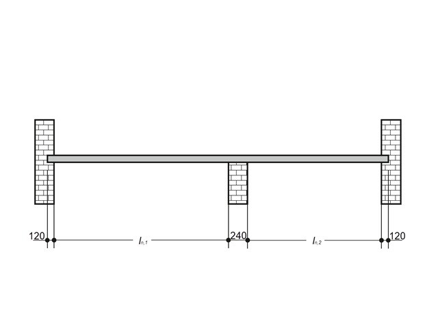
A reinforced concrete slab inside a building is to be designed as a 1.0 m stripe with members. The floor slab is uniaxially spanned and runs through two spans. The slab is fixed on masonry walls with free-rotating supports. The middle support has a width of 240 mm and the two edge supports have a width of 120 mm. The two spans are subjected to an imposed load of category C: congregation areas.
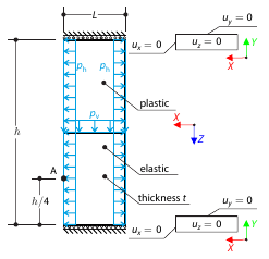
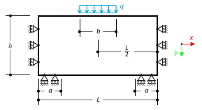
Determine the maximum deformation of a wall divided into two equal parts. The upper and lower parts are made of an elasto-plastic and an elastic material, respectively, and both end planes are restricted to move in the vertical direction. The wall's self-weight is neglected; its edges are loaded with horizontal pressure ph, and the middle plane by vertical pressure.
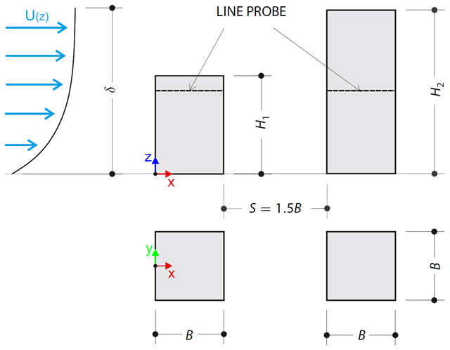
The verification example describes pressure loads on the walls of buildings in tandem arrangement located at ground level. The buildings are simplified to rectangular objects and scaled down while maintaining the elevation ratios. The pressure distribution on the walls of the model of a medium-high building was conducted by an experiment. The chosen results (pressure coefficient Cp) are compared with the measured values.
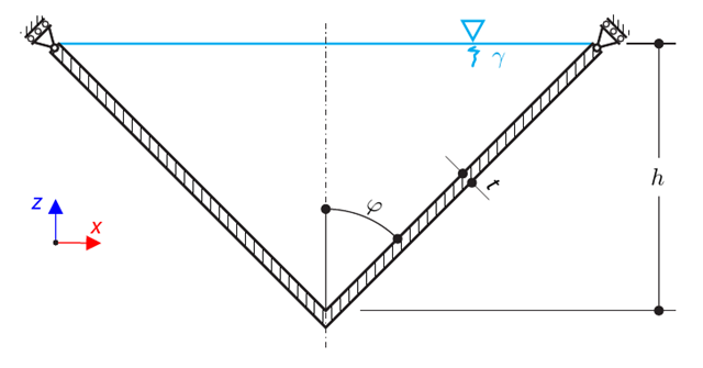
A thin-walled conical vessel is filled with water. Thus, it is loaded by hydrostatic pressure. While neglecting self-weight, determine the stresses in the surface line and circumferential direction. The analytical solution is based on the theory of thin-walled vessels. This theory was introduced in Verification Example 0084.
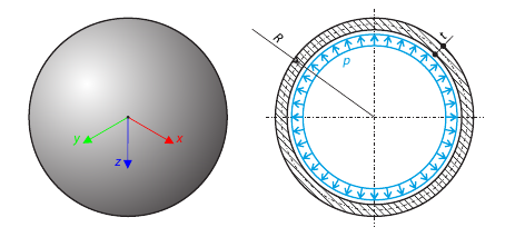
A thin-walled spherical vessel is loaded by inner pressure. While neglecting self‑weight, determine the von Mises stress and the radial deflection of the vessel.

This example is a modification of Verification Example 0061; the only difference is that the material of the vessel is incompressible. An open‑ended, thick‑walled vessel is loaded by both inner and outer pressure. While neglecting self‑weight, the radial deflection of the inner and the outer radius is determined.
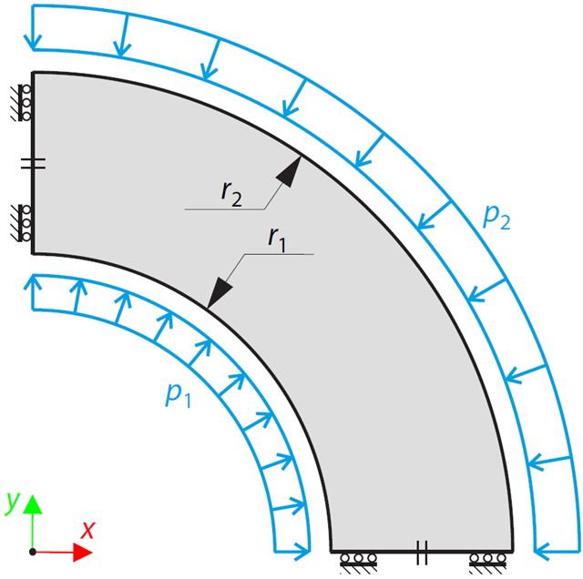
An open-ended, thick-walled vessel is loaded by inner and outer pressure (therefore, there is no axial stress). While neglecting self-weight, the radial deflection of the inner and the outer radius is determined.
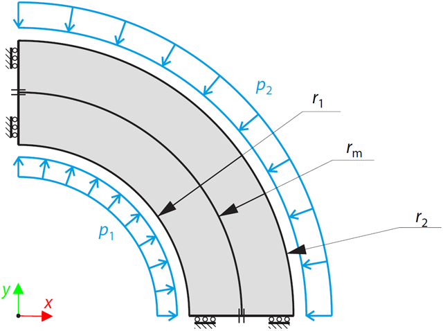
A two-layered, open-ended, thick-walled vessel is loaded by inner and outer pressure; therefore, there is no axial stress. While neglecting self‑weight, the radial deflection of the inner and outer radius, and the pressure (radial stress) in the middle radius is determined.
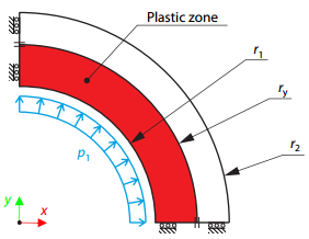
A thick-walled vessel is loaded by an inner pressure such that the vessel reaches an elastic-plastic state. While neglecting self‑weight, the analytical and numerical solutions for the radial position of the plastic zone border (under the Tresca hypothesis) are determined and compared.
A masonry wall is exposed to a distributed load in the middle of its upper section. The Isotropic Masonry 2D material model is compared with the Isotropic Linear Elastic model, with surface stiffness property Without Tension in the nonlinear calculation.
A thin-walled cantilever of a QRO-profile is fully fixed on the left end and warping is enabled. The cantilever is subjected to torque. Small deformations are considered, and the self-weight is neglected. Determine the maximum rotation, primary moment, secondary moment, and warping moment. The verification example is based on the example introduced by Gensichen and Lumpe.
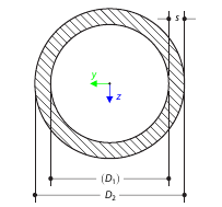
Determine the torsional constant for the cross-section of the tube (annular area) analytically, and compare the results with the numerical solution in RFEM 5 and RSTAB 8 for various wall thicknesses.