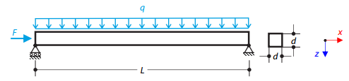
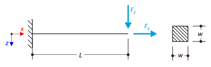
A steel beam with a square cross-section is loaded with an axial force and distributed loading. The image shows the calculation of the maximum bending deflection and critical load factor according to the second-order analysis.
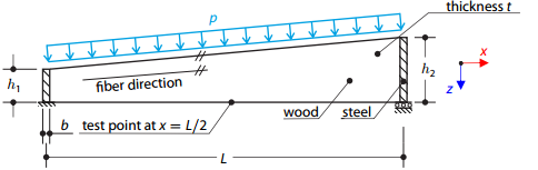
A timber beam reinforced by two steel plates at the ends is loaded by pressure. The wood fibers are parallel to the upper loaded side of the beam. The plastic surface is described according to the Tsai-Wu plasticity theory.
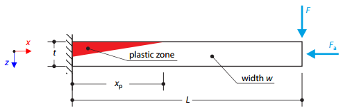
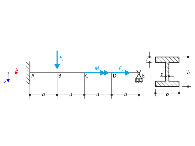
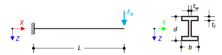
A cantilever is fully fixed on the left end and loaded by a transverse force and an axial force on the right end. The tensile strength is zero and the behavior in the compression remains elastic.
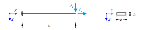
Prove that coupling different dimensional elements does not affect the results. A cantilever with a rectangular cross-section is fixed at one end and loaded at the other by concentrated forces. Neglecting its self-weight and assuming only small deformations, determine the cantilever's maximum deflections.
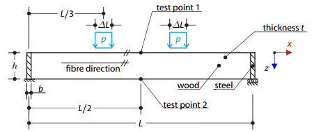
A timber beam reinforced by two steel plates at the ends is loaded by pressure. The wood fibers are parallel to the upper loaded side of the beam. The plastic surface is described according to the Tsai-Wu plasticity theory.
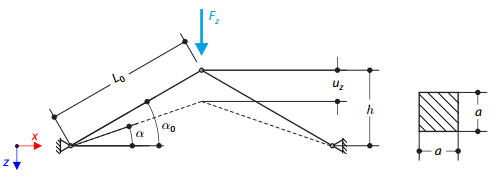
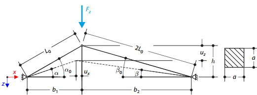
A structure is made of two trusses, which are embedded into the hinge supports. The structure is loaded by concentrated force. The self-weight is neglected. Determine the relationship between the loading force and the deflection, considering large deformations.
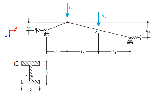
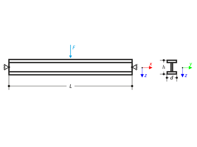
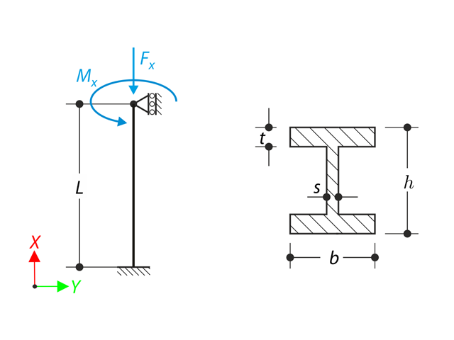
A structure made of I-profile trusses is supported on both ends by spring sliding supports and loaded by transversal forces. The self-weight is neglected in this example. Determine the deflection of the structure, the bending moment, the normal force in the given test points, and the horizontal deflection of the spring supports.
A beam is fully fixed (warping is restricted) on the left end and supported by a fork support (warping is enabled) on the right end. The beam is subjected to a torque, longitudinal force, and transverse force. Determine the behavior of the primary torsional moment, secondary torsional moment, and warping moment. The verification example is based on the example introduced by Gensichen and Lumpe.
A beam pinned at both ends is loaded with concentrated force in the middle. Neglecting its self-weight and shear stiffness, determine the beam's maximum deflection, normal force, and moment at the mid-span, assuming the second- and third-order analysis.
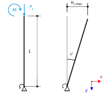
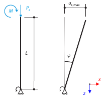
Consider a rigid scaffolding tube, fixed at the bottom using the Scaffolding Nodal Support and loaded by both a moment and a force. Self-weight is not considered. Considering an infinitely rigid beam, determine the maximum radial deflection.
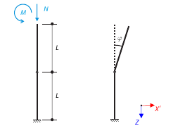
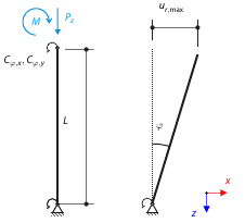
Consider a scaffolding tube connection subjected to an axial force and a moment. Self-weight is not considered. The material of the tube is idealized as perfectly rigid. All geometrical non-linearities are ignored. Determine the angle of deflection.
A console is loaded by concentrated force at its free end. Determine the maximum deflection of the console using large deformation analysis.
A cantilever is loaded by a transversal and an axial force on the right end and is fully fixed on the left end. The problem is described by the following set of parameters. The problem is solved by using the geometrically linear analysis, second-order analysis, and large deformation analysis.
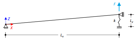
A slightly sloped member is loaded by concentrated force, held by a spring at one end, and supported at the other end. Assuming large deformations and neglecting the member's self-weight, determine its maximum upward deflection.
A structure is made of two trusses of unequal length, which are embedded into the hinge supports. The structure is loaded by concentrated force. The self-weight is neglected. Determine the relationship between the loading force and the deflection, considering large deformations.
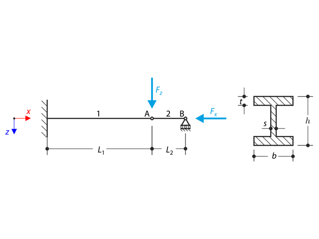
A structure made of an I-profile is fully fixed on the left end and embedded into the sliding support on the right end. The structure consists of two segments. The self-weight is neglected in this example. Determine the maximum deflection of the structure, the bending moment on the fixed end, the rotation of segment 2, and the reaction force at point B by means of the geometrically linear analysis and the second-order analysis. The verification example is based on the example introduced by Gensichen and Lumpe.
A member with the given boundary conditions is loaded by torsional moment and axial force. Neglecting its self-weight, determine the beam's maximum torsional deformation as well as its inner torsional moment, defined as the sum of a primary torsional moment and torsional moment caused by the normal force. Provide a comparison of those values while assuming or neglecting the influence of the normal force. The verification example is based on the example introduced by Gensichen and Lumpe.
Consider a rigid scaffolding tube, fixed at the bottom using the Scaffolding Nodal Support and loaded by both a moment and a force. Calculate the maximum deflection with consideration of initial slippage.
Consider a rigid scaffolding tube, fixed at the bottom using the Scaffolding Nodal Support and loaded by both a moment and a force. Calculate the maximum radial deflection by exceeding the capacity of the scaffolding support.
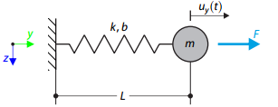
A single mass system is subjected to loading force. Determine the deflection of the system.
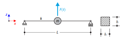
A long, thin beam is carrying a concentrated mass and is loaded by a time-dependent force. It is simply supported. The problem is described using the following parameters. Determine the deflections in the given test times.
Time history analysis of a cantilever beam (SDOF system) excited by a periodic function. Vertical deformations and accelerations calculated with direct integration and modal analysis in RF‑/DYNAM Pro - Forced Vibrations are compared with the analytical solution.
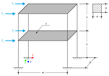
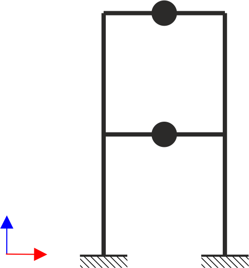
This example serves as a demonstration of the diaphragm constraint. The application is shown on a two-story structure. The structure is loaded by means of lateral forces according to Figure 1. Determine the maximum deflection of the structure ux in the direction of the loading forces using both the diaphragm constraint and the plate model of the floor.
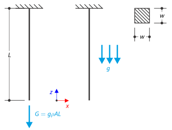
A rod with a square cross-section is fixed on the top end. The rod is loaded by self-weight. For comparison, the example is also modeled with the concentrated force load, the value of which is equal to the gravity. The aim of this verification example is to show the difference between these types of loading, although the total loading force is equal.
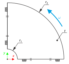
A compact disc (CD) rotates at a speed of 10,000 rpm. Therefore, it is subjected to centrifugal force. The problem is modeled as a quarter model. Determine the tangential stress on the inner and outer diameters and the radial deflection of the outer radius.
A two‑story, single‑bay frame structure is subjected to earthquake loading. The modulus of elasticity and cross‑section of the frame beams are much larger than those of the columns, so the beams can be considered rigid. The elastic response spectrum is given by the standard SIA 261/1:2003. Neglecting self-weight and assuming the lumped masses are at the floor levels, determine the natural frequencies of the structure. For each frequency obtained, specify the standardized displacements of the floors as well as equivalent forces generated using the elastic response spectrum according to the standard SIA 261/1.2003.
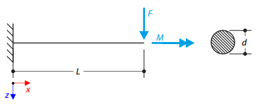
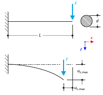
A cantilever with a circular cross‑section is loaded by a concentrated bending force and torque. The aim of this verification example is to compare the reduced stress according to the von Mises and Tresca theories.
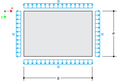
A rectangular membrane is tensioned by a line force. Determine the natural frequencies of the given membrane.
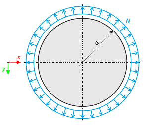
A circular membrane is tensioned by a line force. Determine the natural frequencies of the circular membrane.
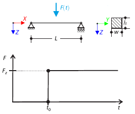
A concentrated force is suddenly applied at the mid‑span of a simply supported beam at a given time. Considering only the small deformation theory, determine the maximum deflection of the beam.