
This example compares the effective lengths and critical load factor, which can be calculated in RFEM 6 using the Structure Stability add-on, with a manual calculation. The structural system is a rigid frame with two additional hinged columns. This column is loaded by vertical concentrated loads.
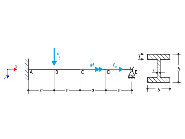
A beam is fully fixed (warping is restricted) on the left end and supported by a fork support (free warping) on the right end. The beam is subjected to a torque, longitudinal force, and transverse force. Determine the behavior of the primary torsional moment, secondary torsional moment and warping moment. The verification example is based on the example introduced by Gensichen and Lumpe (see reference).

In the current validation example, we investigate wind pressure coefficient (Cp) of flat roof and walls with ASCE7-22 [1]. In the section 28.3 (Wind loads - main wind force resisting system) and Figure 28.3-1 (load case 1), there is a table which shows Cp value for different roof angle.
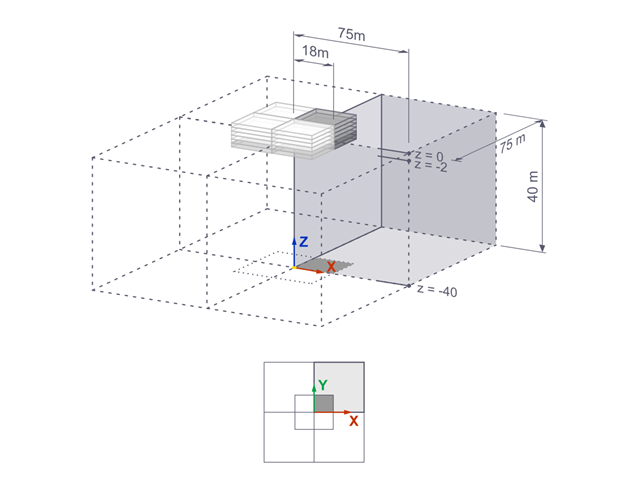
The settlements of a rigid square foundation on a lacustrine clay [1] are calculated with RFEM. One quarter of the foundation is modelled. The foundation has a width of 75.0 m in both sides. Construction stages are used to generate the results.

Consider an ASTM A992 W 18x50 beam forspan and uniform dead and live loads as shown in Figure 1. The member is limited to a maximum nominal depth of 18 inches. The live load deflection is limited to L/360. The beam is simply supported and continuously braced. Verify the available flexural strength of the selected beam, based on LRFD and ASD.

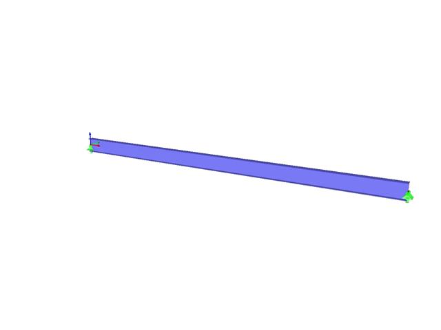
An ASTM A992 W 24×62 beam with end shears of 48.000 and 145.000 kips from the dead and live loads, respectively, is shown in Figure 1. Verify the available shear strength of the selected beam, based on LRFD and ASD.
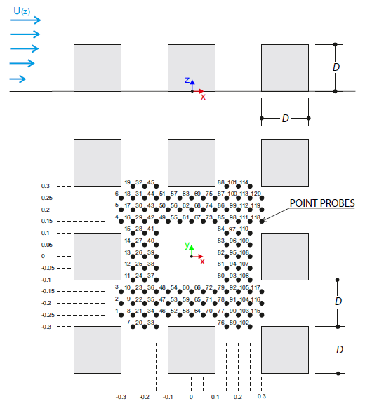
The verification example describes wind loads in several wind directions on a model of a group of buildings. The model consists of eight cubes. The velocity fields obtained by the RWIND simulation are compared with the measured values from the experiment. The experimental data are measured using a thermistor anemometer in the wind tunnel.
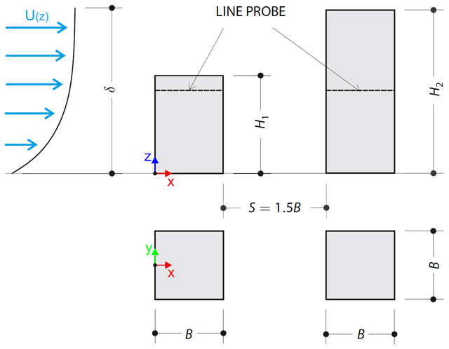
The verification example describes pressure loads on the walls of buildings in tandem arrangement located at ground level. The buildings are simplified to rectangular objects and scaled down while maintaining the elevation ratios. The pressure distribution on the walls of the model of a medium-high building was conducted by an experiment. The chosen results (pressure coefficient Cp) are compared with the measured values.
The verification example describes the steady-state flow around an isolated building (scaled model).The example is given by the Architectural Institute of Japan (AIJ). The chosen results (velocity magnitude) are compared with the measured values.
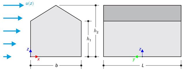
This verification example compares wind load calculations on a duopitch roof building using the ASCE 7-16 standard and using CFD simulation in RWIND Simulation. The building is defined according to the sketch and the inflow velocity profile taken from the ASCE 7-16 standard.

This verification example compares wind load calculations on a flat roof building using the ASCE 7-16 standard and using CFD simulation in RWIND Simulation. The building is defined according to the sketch and the inflow velocity profile taken from the ASCE 7-16 standard.
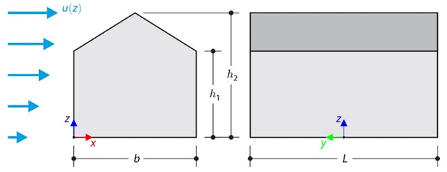
The verification example compares wind load calculation on a building with a duopitch roof using the standard EN 1991-1-4 and using CFD simulation in RWIND Simulation. The building is defined according to the sketch, and the inflow velocity profile is taken according to the standard EN 1991-1-4.
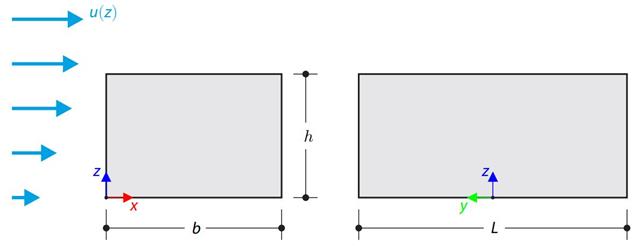
The verification example compares wind load calculation on a building with a flat roof using the standard EN 1991-1-4 and using CFD simulation in RWIND Simulation. The building is defined according to the sketch, and the inflow velocity profile is taken according to the standard EN 1991-1-4.
Consider an ASTM A992 W 18×50 beam forspan and uniform dead and live loads as shown in Figure 1. The member is limited to a maximum nominal depth of 18 inches. The live load deflection is limited to L/360. The beam is simply supported and continuously braced. Verify the available flexural strength of the selected beam, based on LRFD and ASD.
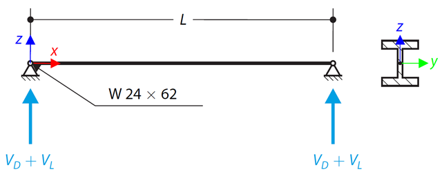
An ASTM A992 W 24×62 beam with end shears of 48.000 and 145.000 kips from the dead and live loads, respectively, is shown in Figure 1. Verify the available shear strength of the selected beam, based on LRFD and ASD.
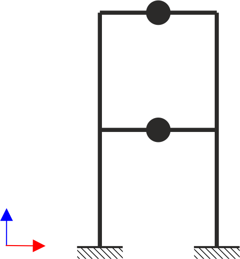
A two‑story, single‑bay frame structure is subjected to earthquake loading. The modulus of elasticity and cross‑section of the frame beams are much larger than those of the columns, so the beams can be considered rigid. The elastic response spectrum is given by the standard SIA 261/1:2003. Neglecting self-weight and assuming the lumped masses are at the floor levels, determine the natural frequencies of the structure. For each frequency obtained, specify the standardized displacements of the floors as well as equivalent forces generated using the elastic response spectrum according to the standard SIA 261/1.2003.
A beam is fully fixed (warping is restricted) on the left end and supported by a fork support (warping is enabled) on the right end. The beam is subjected to a torque, longitudinal force, and transverse force. Determine the behavior of the primary torsional moment, secondary torsional moment, and warping moment. The verification example is based on the example introduced by Gensichen and Lumpe.
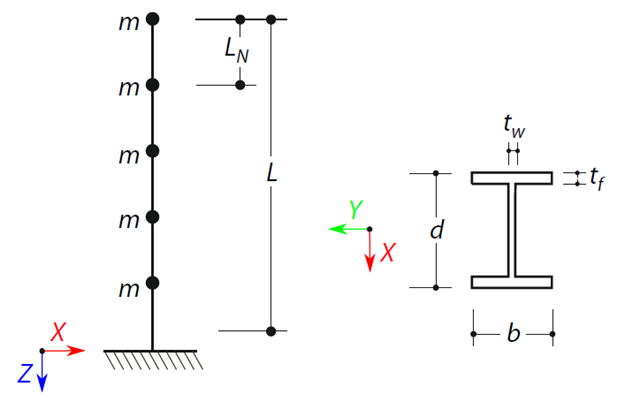
A cantilever beam with an I-beam cross-section of length L is defined. The beam has five mass points with masses m acting in the X-direction. The self-weight is neglected. The frequencies, mode shapes, and equivalent loads of this 5-DOF system are analytically calculated and compared with the results from RSTAB and RFEM.