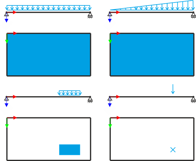
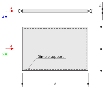
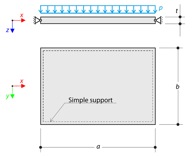
A simply supported rectangular plate is subjected to different load types. Assuming only the small deformation theory and neglecting self-weight, determine the deflection at its centroid for each load type.
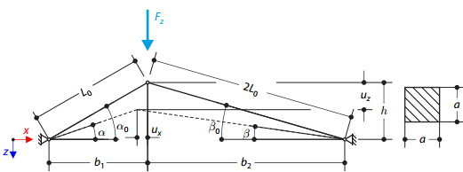
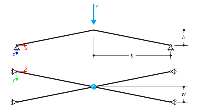
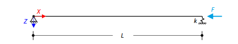
A structure is made of two trusses of unequal length, which are embedded into the hinge supports. The structure is loaded by concentrated force. The self-weight is neglected. Determine the relationship between the loading force and the deflection, considering large deformations.
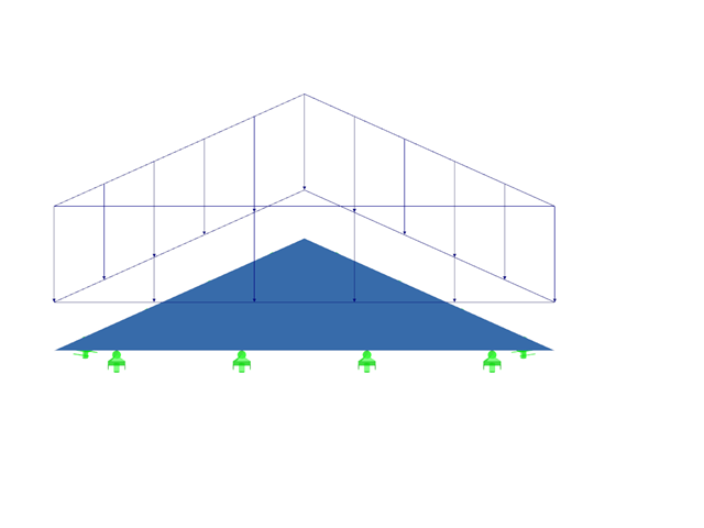
A simply supported equilateral triangular plate is subjected to a uniformly distributed transverse load. Assuming the small deformation theory and neglecting self‑weight, the maximum out‑of‑plane deflection of the plate is determined.
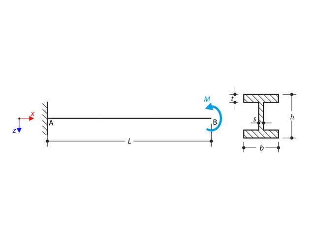
An I-profile cantilever is supported on the left end and loaded by torque. The aim of this example is to compare the fixed support with the fork support and to investigate the behavior of some representative quantities. Comparison is also made to the solution by means of plates. Small deformations are considered, and the self-weight is neglected. Determine the rotation in the midpoint of the cantilever, and in case of the member entity with warping, determine the values of the primary torsional moment, the secondary torsional moment, and the warping moment both on the left end (point A) and the right end (point B).
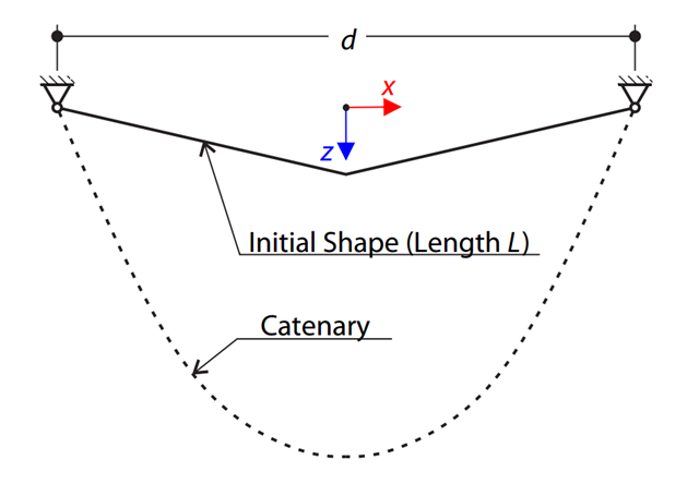
A very stiff cable is suspended between two supports. Determine the equilibrium shape of the cable (the catenary), consider the gravitational acceleration, and neglect the stiffness of the cable. Verify the position of the cable at the given test points.
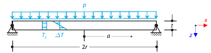
Determine the maximum deflection and maximum radial moment of a simply supported circular plate subjected to uniform pressure, uniform temperature, and differential temperature.

Using AISC Manual tables, determine the available compressive and flexural strengths and whether the ASTM A992 W14x99 beam has sufficient available strength to support the axial forces and moments shown in Figure 1, obtained from a second-order analysis that includes P-𝛿 effects.
Using AISC Manual tables, determine the available compressive and flexural strengths and whether the ASTM A992 W14x99 beam has sufficient available strength to support the axial forces and moments shown in Figure 1, obtained from a second-order analysis that includes P-𝛿 effects.
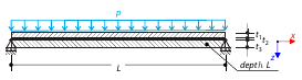
Determine the maximum displacement, in-plane stresses, and stress ratios of a simply supported double-pane glass plate with a foil between both glass panes subjected to uniform pressure.
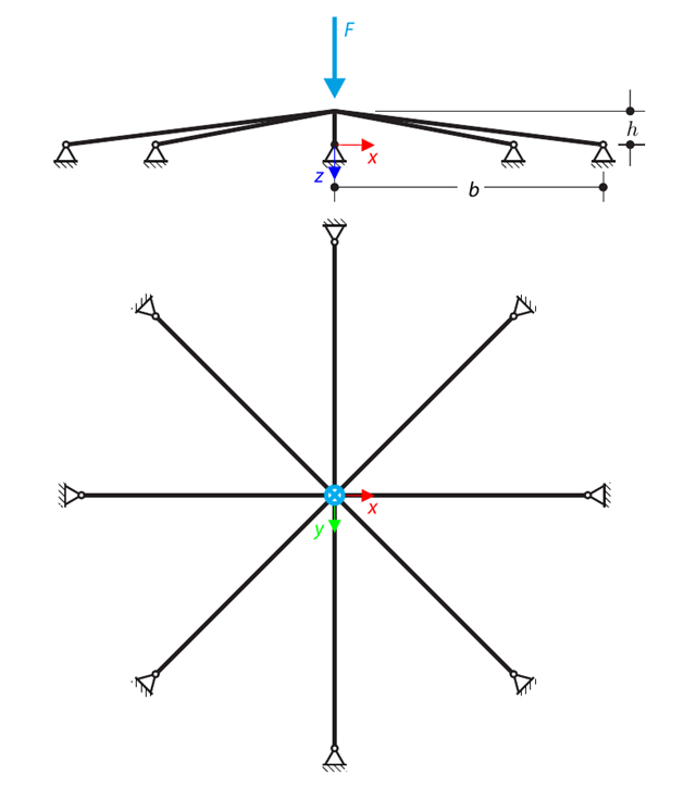
A symmetrical shallow structure is made of eight equal truss members, which are embedded into hinge supports. The structure is loaded by a concentrated force and alternatively by imposed nodal deformation over the critical limit point when the snap-through occurs. Imposed nodal deformation is used in RFEM 5 and RSTAB 8 to obtain the full equilibrium path of the snap-through. The self-weight is neglected in this example. Determine the relationship between the actual loading force and the deflection, considering large deformation analysis. Evaluate the load factor at the given deflections.
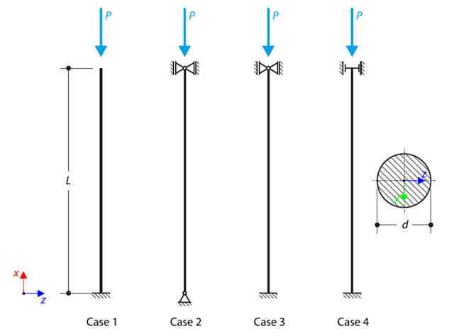
A strut with a circular cross-section is supported according to four basic cases of Euler buckling and subjected to pressure force. Determine the critical load.
A structure is made of four truss members, which are embedded into hinge supports. The structure is loaded by a concentrated force and alternatively by imposed nodal deformation over the critical limit point, when snap-through occurs. Imposed nodal deformation is used in RFEM 5 and RSTAB 8 to obtain the full equilibrium path of the snap-through. The self-weight is neglected in this example. Determine the relationship between the actual loading force and the deflection, considering large deformation analysis. Evaluate the load factor at given deflections.
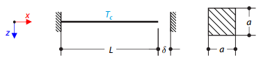
A steel rod between two rigid supports with a gap is loaded by a temperature difference. While neglecting self‑weight, determine the total deformation of the rod and its internal axial force.
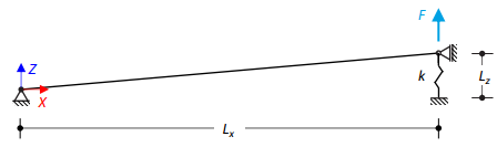
A slightly sloped member is loaded by concentrated force, held by a spring at one end, and supported at the other end. Assuming large deformations and neglecting the member's self-weight, determine its maximum upward deflection.
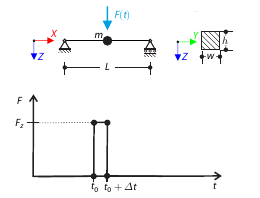
A concentrated force is applied for a short period of time at the mid‑span of a simply supported beam. Considering only the small deformation theory and assuming that the mass of the beam is concentrated at its mid‑span, determine its maximum deflection.
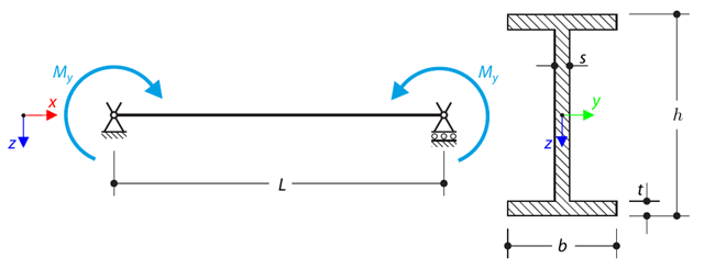
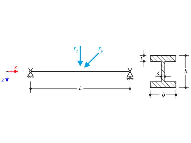
A simply supported beam is loaded by pure bending. Determine the critical load and corresponding load factor due to lateral buckling.
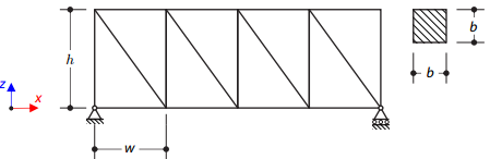
A planar truss structure is simply supported. The aim of this verification example is to determine the natural frequencies of the structure.
A rectangular steel plate of dimensions is simply supported at its edges. Determine the natural frequencies of the rectangular plate.
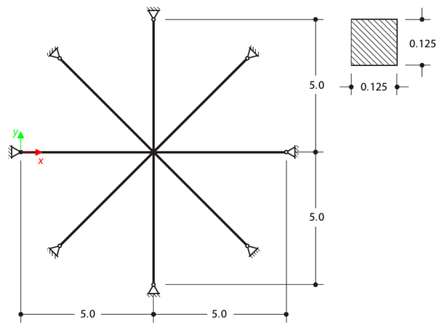
Determine the first sixteen natural frequencies of a double cross with a square cross-section. Each of the eight arms is modeled by means of four beam elements and has a pin support at the end (the x- and y-deflections are restricted). The vibrations are considered only in plane xy. The problem is defined according to The Standard NAFEMS Benchmarks.
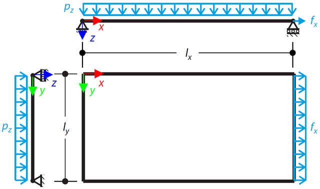
A simply supported rectangular Kirchhoff plate is subjected to both uniform lateral pressure and stretched by a distributed load. The maximum out-of-plane deflection is determined by assuming small deformations.
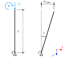
Consider a rigid scaffolding tube, fixed at the bottom using the Scaffolding Nodal Support and loaded by both a moment and a force. Self-weight is not considered. Considering an infinitely rigid beam, determine the maximum radial deflection.
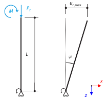
Consider a rigid scaffolding tube, fixed at the bottom using the Scaffolding Nodal Support and loaded by both a moment and a force. Calculate the maximum deflection with consideration of initial slippage.
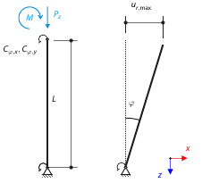
Consider a rigid scaffolding tube, fixed at the bottom using the Scaffolding Nodal Support and loaded by both a moment and a force. Calculate the maximum radial deflection by exceeding the capacity of the scaffolding support.
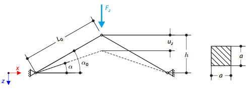
A structure is made of two trusses, which are embedded into the hinge supports. The structure is loaded by concentrated force. The self-weight is neglected. Determine the relationship between the loading force and the deflection, considering large deformations.
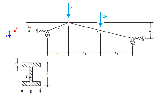
A structure made of I-profile trusses is supported on both ends by spring sliding supports and loaded by transversal forces. The self-weight is neglected in this example. Determine the deflection of the structure, the bending moment, the normal force in the given test points, and the horizontal deflection of the spring supports.
A structure made of an I-profile is embedded into the fork supports. The axial rotation is restricted on both ends while warping is enabled. The structure is loaded by two transverse forces in the middle. The verification example is based on the example introduced by Gensichen and Lumpe.
An axially loaded steel beam with a square cross-section is pinned at one end and spring-supported at the other. Two cases with different spring stiffnesses are considered. The verification example solves the calculation of the load factors of the beam in the image using the linear stability analysis.
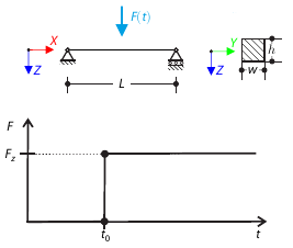
A concentrated force is suddenly applied at the mid‑span of a simply supported beam at a given time. Considering only the small deformation theory, determine the maximum deflection of the beam.
A thin rectangular orthotropic plate is simply supported and loaded by uniformly distributed pressure. The directions of axes x and y coincide with the principal directions. While neglecting self-weight, determine the maximum deflection of the plate.
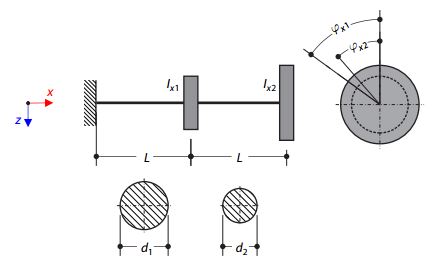
A double‑mass system consists of two shafts and two masses represented by the corresponding moments of inertia, concentrated in a given distance as nodal masses. The left shaft is fixed, and the right mass is free. Neglecting the self‑weight of the shafts, determine the torsional natural frequencies of the system.