


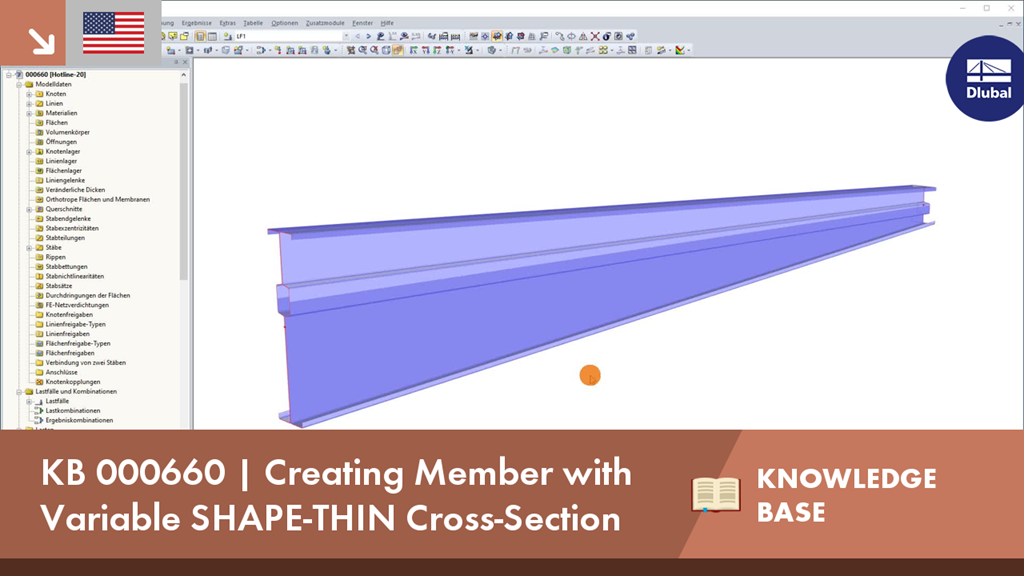
In RFEM and RSTAB, it is possible to analyze members with a variable cross-section, which can also consist of freely defined SHAPE‑THIN cross-sections. For the determination of internal forces and deformations, the cross-section properties are interpolated.