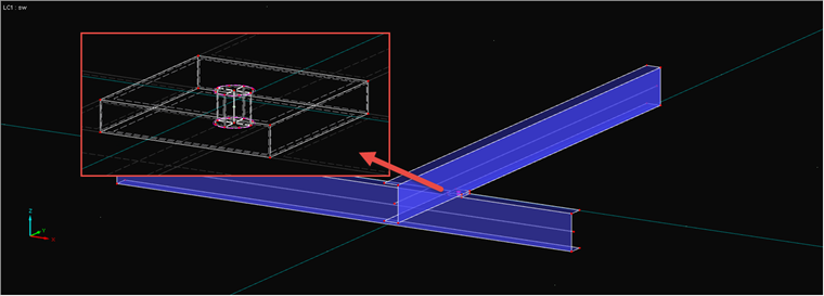
Depending on the requirements, there are various options. As an example, two intersecting channel sections serve as surface models, as shown in Image 01. The spacing of the sections is comprised of one-half the surface thickness in each case, since center surfaces are modeled in RFEM.
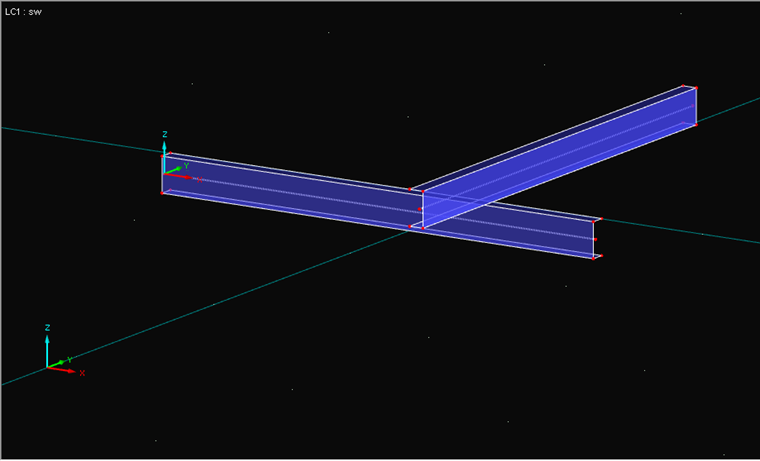
For Option 1, a bolt is modeled between both surfaces. It is important to ensure that the load introduction of a single node into a surface creates a singularity (Image 02). Below, you will find a link to an article showing how to prevent this kind of point load introduction and a link to an article showing how to model a hole bearing. In the case of this simpler option, the bolt must also absorb compressive forces, as the surfaces do not rest on each other.
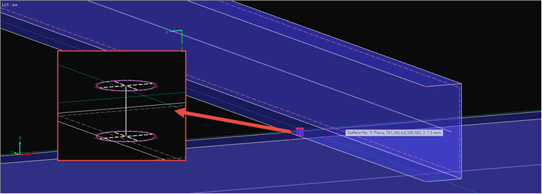
Option 2 additionally uses a contact solid (see the description by clicking the link). In the contact solid, you can set how the forces should be transferred. If the contact solid is in tension, the bolt will be in tension and the surfaces in compression (Image 03).