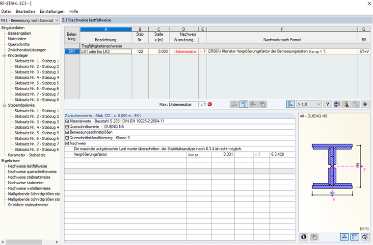
16 August 2019
003491
What is the meaning of the warning message ER061) Minimum amplifier of design loads <1?
Answer
Keywords
Lateral-torsional buckling Unstable Amplifier
Downloads
Contact us
Did you find your question?
If not, contact us via our free e-mail, chat, or forum support, or send us your question via the online form.
Recommended Events
Eurocode 3 | Steel structures according to DIN EN 1993-1-1
Online Training 18 March 2021 8:30 AM - 12:30 PM CET
Eurocode 3 | Steel structures according to DIN EN 1993-1-1
Online Training 6 May 2021 8:30 AM - 12:30 PM
Stability Design in Steel Construction with RFEM and RSTAB
Webinar 1 December 2020 2:00 PM - 2:45 PM CET
Designing Cold-Formed Steel Sections According to Eurocode 3
Webinar 30 April 2020 3:00 PM - 3:45 PM
Membrane Structures with Wind Loads From CFD Wind Simulation
Webinar 24 March 2020 3:00 PM - 4:15 PM CET
Videos
KB 001649 | Stability Analysis of a Purlin With I-Section Without Lateral and Torsional Restraint
Length min
KB 000585 | Calculation of warping springs for consideration in lateral -torsional buckling analy...
Length 1:30 min
Models to Download
Knowledge Base Articles
New
Manual adjustment of the buckling curve according to EN 1993-1-1
The RF-/STEEL EC3 add-on module automatically transfers the buckling line to be used for the flexural buckling analysis for a cross-section from the cross-section properties. In particular for general cross -sections, but also for special cases, the assignment of the buckling line can be adjusted manually in the module input.
Screenshots
Product Features Articles

SHAPE-THIN | Cold-Formed Sections
SHAPE-THIN determines the effective cross-sections according to EN 1993-1-3 and EN 1993-1-5 for cold-formed sections. You can optionally check the geometric conditions for the applicability of the standard specified in EN 1993‑1‑3, Section 5.2.
The effects of local plate buckling are considered according to the method of reduced widths and the possible buckling of stiffeners (instability) is considered for stiffened sections according to EN 1993-1-3, Section 5.5.
As an option, you can perform an iterative calculation to optimize the effective cross-section.
You can display the effective cross-sections graphically.
Read more about designing cold-formed sections with SHAPE-THIN and RF-/STEEL Cold-Formed Sections in this technical article: Design of a Thin-Walled, Cold-Formed C-Section According to EN 1993-1-3.
Frequently Asked Questions (FAQ)
- In RF-/STEEL EC3, is the "Elastic design (also for cross-section class 1 and 2)" option under "Details → Ultimate Limit State" considered for the stability analysis when activated?
-
I design an eccentrically modeled wall beam in RF‑/STEEL Warping Torsion, which is loaded transversely with a distributed load. While the bending moments in the main program result in zero at the member start and member end due to the hinges, the RF‑/STEEL Warping Torsion add-on module displays moments at these locations, which incorrectly reduces the span moment.
How do I get the boundary moments equal to zero at this point? - How can I design any SHAPE‑THIN cross-section in detail in RFEM or RSTAB?
- When entering data in the RF‑/STEEL EC3 add-on module, I get the error message "Incorrect location of the intermediate lateral restraint". Why?
- I perform a stability analysis of a beam for lateral-torsional buckling. Why is the modified reduction factor χLT,mod used in the design according to DIN EN 1993‑1‑1, 6.3.3 Method 2? Is it possible to deactivate this?
- I need to define different types of lateral intermediate restrains for a single element in RF-/STEEL EC3. Is this possible?
- I compare the flexural buckling design according to the equivalent member method and the internal forces according to the linear static analysis with the stress calculation according to the second-order analysis including imperfections. The differences are very large. What is the reason?
- Why are the equivalent member designs grayed out in the Stability tab when activating the plastic designs by using the partial internal force method (RF‑/STEEL Plasticity)?
- In the RF‑/STEEL EC3 add-on module, I have selected two bracings with the same size as the shear panel type in the "Parameters" window for a beam to be designed. Thus, the beam should be supported laterally in the middle. Why is the eigenvector arbitrary anyhow?
-
I design a set of members by using the equivalent member method in RF‑/STEEL EC3, but the calculation fails. The system is unstable, delivering the message "Non-designable - ER055) Zero value of the critical moment on the segment."
What could be the reason?
Customer Projects