Question
I have a circular surface with symmetric loading. However, the results are unsymmetric. What can be the reason?
Answer:
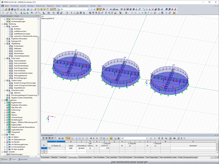
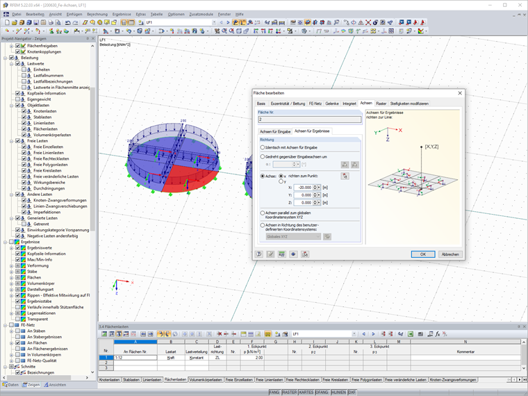
The axis orientation of the surfaces in your model is probably not adjusted. For a circular surface, we recommend specifying the orientation of the axes of the surfaces or the axes of the results of the surfaces.
You can adjust the axes for each surface. In the "Axes" tab, you can find the subtabs "Axes for Input" and "Axes for Results".
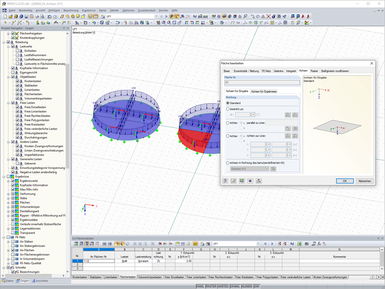
The "Axes for Results" tab adjusts the axes of the surface for the results. Here you can specify the orientation of the axes using a point, for example. A major advantage of this method is that the results are not deleted when adjusting the axes.
The "Axes for Input" tab adjusts the axes of the surface for the orientation and results. Here you can specify the orientation of the axes on a line, for example.
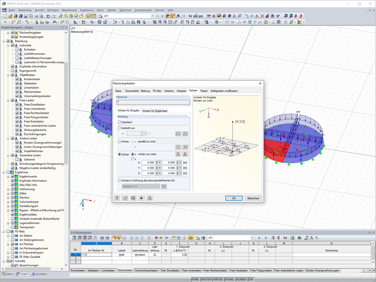
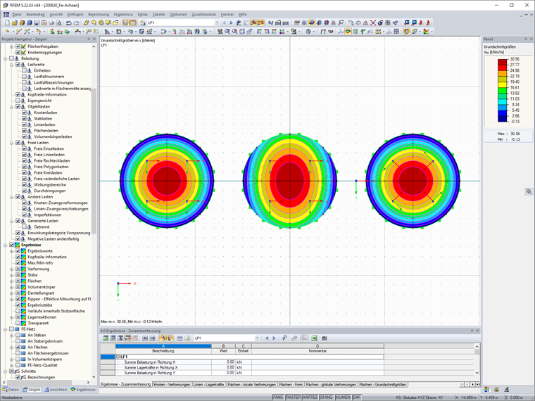
The results of both axis adjustments are the same. For symmetric loading, the expected symmetric results are provided.
Do you have any questions?
In RF-/FOUNDATION Pro, the user can freely select the proportion of the relieving soil pressure by means of the factor kred.
In RFEM 5 and RSTAB 8, it is possible to assign nonlinearities to member hinges. In addition to the nonlinearities "Fixed if" and "Partial activity", you can select "Diagram". If you select the "Diagram" option, you have to specify the according settings for the activity of the member hinge. For the individual definition points, it is necessary to specify the abscissa and ordinate values (deformations or rotations and the according internal forces) that define the hinge.
In RF-/FOUNDATION Pro, you can also consider the concrete cover for the foundation according to EN 1992-1-1.
RFEM 5 allows you to use many different member nonlinearities for designing a model. In the following text, we look at an example of the use of the "slippage" member nonlinearity. The example is a simplified model of a concrete manhole with a square plan view.
The results of solid stresses can be displayed as colored 3D points in the finite elements.
Use the "Independent mesh preferred" option in the FE mesh settings to create an independent FE mesh for the integrated objects. This allows you to generate a significantly more detailed and precise FE mesh for individual objects that are integrated into one another.
In the "Edit Section" dialog box, you can display the buckling shapes of the Finite Strip Method (FSM) as a 3D graphic.
In RFEM 6 and RSTAB 9, you have the option to enter "Visual Objects" as guide objects. You can import the file formats 3ds, stl, and obj.
These objects allow you to create a better reference to the dimensions.
Recommended Products for You