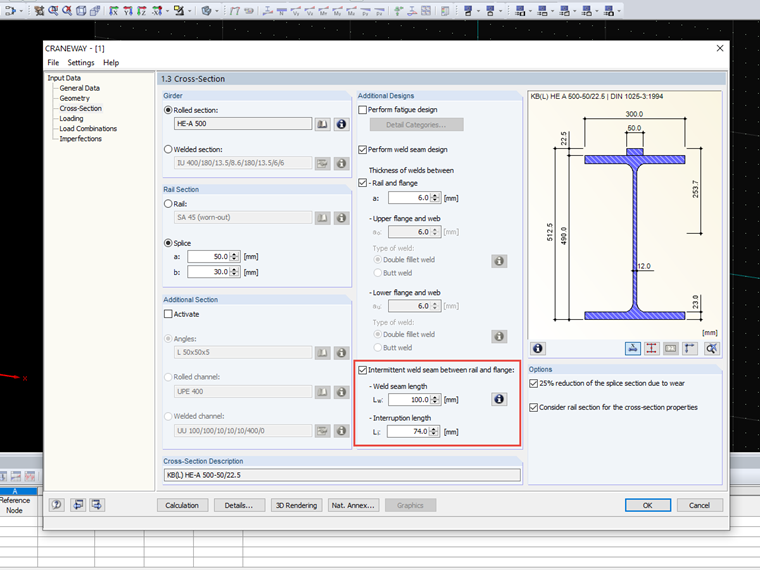
Is it possible to design intermittent welds in the CRANEWAY add-on module?
Answer
Yes, it is possible. The Intermittent weld seam option is suitable if the weld seam between the crane rail and the flange is not continuous. A parallel opposing arrangement is assumed. After you select the check box, you can specify the length of the weld seam and the interruption. These specifications are considered in the design.
On our website, you can also find an interesting technical article about "Ultimate Limit State Design of Rail Welds of Crane Girders According to EN 1993-6."
Keywords
Intermittent weld Intermittent Weld seam
Links
Contact us
Did you find your question?
If not, contact us via our free e-mail, chat, or forum support, or send us your question via the online form.
Recommended Events
Eurocode 3 | Steel structures according to DIN EN 1993-1-1
Online Training 18 March 2021 8:30 AM - 12:30 PM CET
Eurocode 3 | Steel structures according to DIN EN 1993-1-1
Online Training 6 May 2021 8:30 AM - 12:30 PM
Stability Design in Steel Construction with RFEM and RSTAB
Webinar 1 December 2020 2:00 PM - 2:45 PM CET
Designing Cold-Formed Steel Sections According to Eurocode 3
Webinar 30 April 2020 3:00 PM - 3:45 PM
Membrane Structures with Wind Loads From CFD Wind Simulation
Webinar 24 March 2020 3:00 PM - 4:15 PM CET
Videos
Models to Download
Knowledge Base Articles
New
Manual adjustment of the buckling curve according to EN 1993-1-1
The RF-/STEEL EC3 add-on module automatically transfers the buckling line to be used for the flexural buckling analysis for a cross-section from the cross-section properties. In particular for general cross -sections, but also for special cases, the assignment of the buckling line can be adjusted manually in the module input.
Screenshots
Product Features Articles

SHAPE-THIN | Cold-Formed Sections
SHAPE-THIN determines the effective cross-sections according to EN 1993-1-3 and EN 1993-1-5 for cold-formed sections. You can optionally check the geometric conditions for the applicability of the standard specified in EN 1993‑1‑3, Section 5.2.
The effects of local plate buckling are considered according to the method of reduced widths and the possible buckling of stiffeners (instability) is considered for stiffened sections according to EN 1993-1-3, Section 5.5.
As an option, you can perform an iterative calculation to optimize the effective cross-section.
You can display the effective cross-sections graphically.
Read more about designing cold-formed sections with SHAPE-THIN and RF-/STEEL Cold-Formed Sections in this technical article: Design of a Thin-Walled, Cold-Formed C-Section According to EN 1993-1-3.
Frequently Asked Questions (FAQ)
- Is it necessary to enter the loads of a crane for each axle or wheel in the table of crane loads in Window 1.4?
- When doing a calculation, I activated the 'Detailed Calculation' option. Have the support loads already been specified with the reduced dynamic coefficient for dimensioning the substructure?
- What do the abbreviations for the crane loads in the CRANEWAY Add-on Module mean?
- Why do I get large differences for the design of a longitudinally stiffened buckling panel in comparison with the German and Austrian National Annex?
- How can I create a curved or arched section?
- How are the signs for the release results of a line release and line hinges interpreted?
- How can I perform the stability analysis in RF‑/STEEL EC3 for a flat bar supported on edges, such as 100/5? Although the cross-section is rotated by 90° in RFEM/RSTAB, it is displayed as lying flat in RF‑/STEEL EC3.
- How are hot-dip galvanized components considered for fire resistance in the RF‑/STEEL EC3 add-on module?
- How is the rotational stiffness of a buckling stiffener determined in PLATE‑BUCKLING?
- In RF-/STEEL EC3, is the "Elastic design (also for cross-section class 1 and 2)" option under "Details → Ultimate Limit State" considered for the stability analysis when activated?
Customer Projects