Arrangement Options of Rail Fillet Welds
There are two variants of intermittent fillet welded connections. These are shown in the following image from [2].
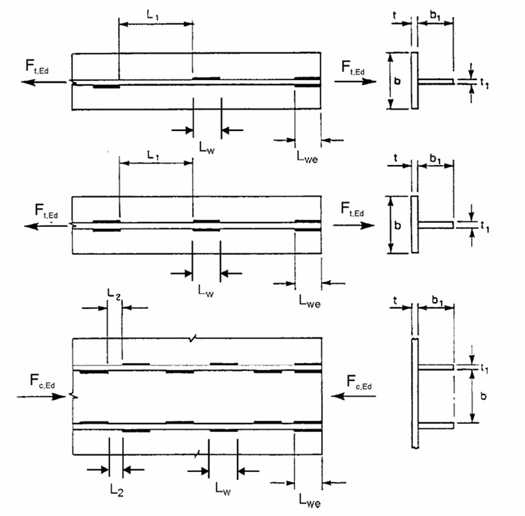
Weld sections can be arranged either on opposite sides or staggered. The staggered arrangement is disadvantageous for the design since only one weld can be used for the transfer of horizontal loads. The third option that is not shown in the image above is, of course, a continuous fillet weld along the entire rail length.
Effective Loaded Length
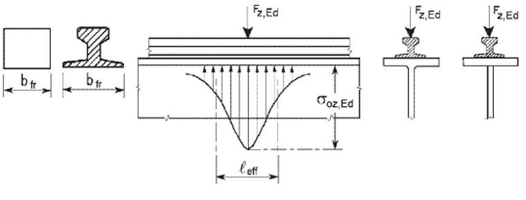
The determination of the corresponding weld stresses requires the calculation of effective loaded lengths. EN 1993‑6 differentiates between three options and provides the corresponding formulas for the calculation of leff in Table 5.1.
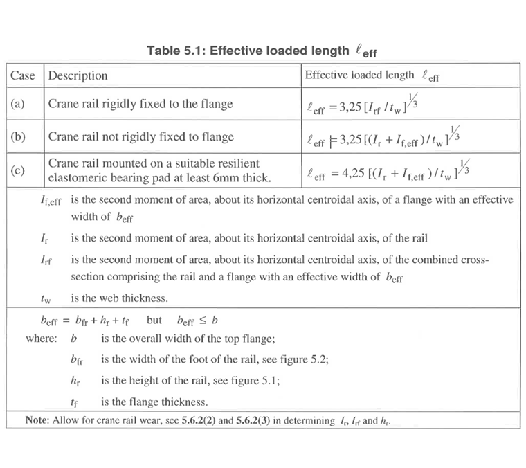
In this case, leff refers to the underside of the top flange. However, the upper surface of the top flange governs for the weld design. Therefore, leff is reduced by double flange thickness tf.
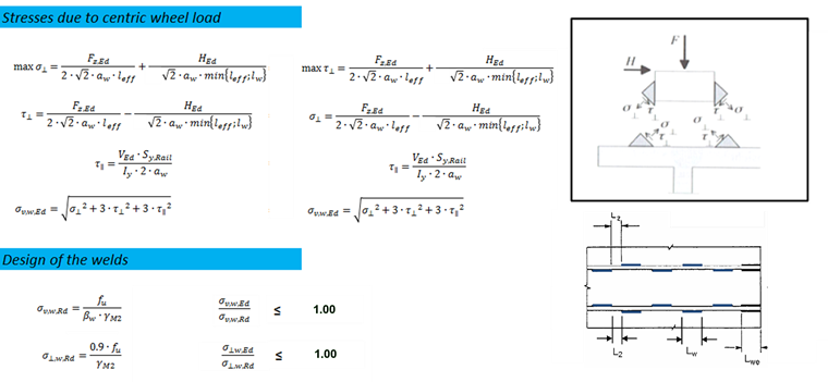
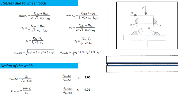
Ultimate Limit State Design
Rail weld stresses are calculated according to the Directional Method specified in [2]. In this case, the stresses refer to the bisecting surface of the fillet weld. According to [2], (NA) Section 4.5.2, the minimum structural thicknesses must be kept for the weld. The standard requires a weld of a minimum thickness of at least 3 mm or the application of the following formula:
The eccentric wheel load of 1/4 of the rail head width is not taken into account in the ultimate limit state according to EN 1993-6. Therefore, the design due to wheel loading is always performed.
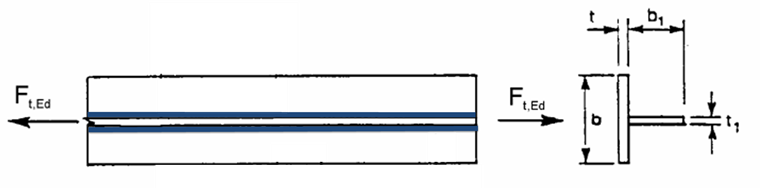
Case 1: Continuous Rail Weld
For intermittent rail fillet welds, it is necessary to check whether the weld length lw is less than the calculated loaded length leff. Generally, the minimum of both values is governing for the design.
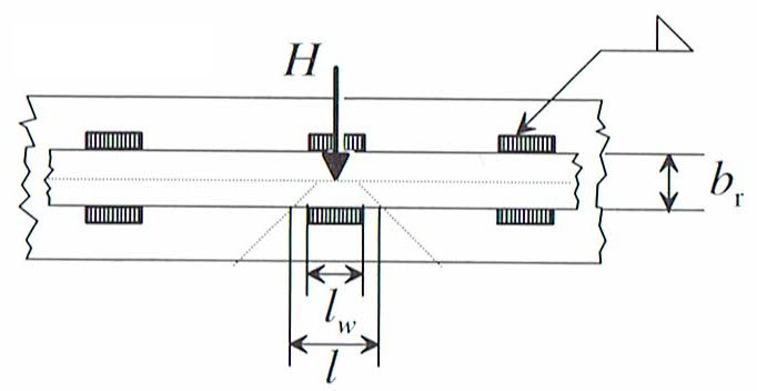
Case 2: Intermittent Rail Weld on Opposite Sides
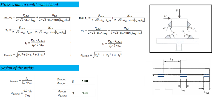
Case 3: Staggered Intermittent Rail Weld
Since the horizontal load is only applied to a weld section in the case of the staggered arrangement of welds, Divisor 2 is omitted in terms of HEd.