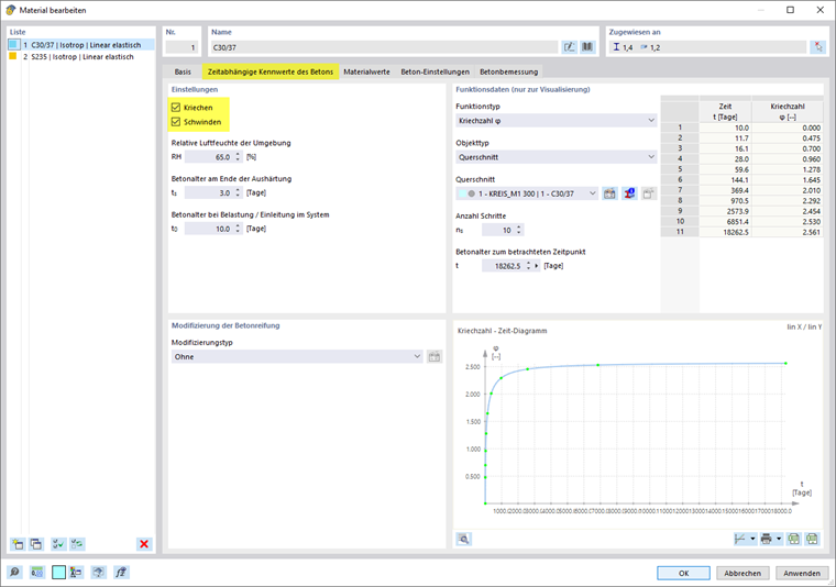
You can activate the creep and shrinkage to be considered for the concrete design in the Edit Material dialog box (see Image 01).
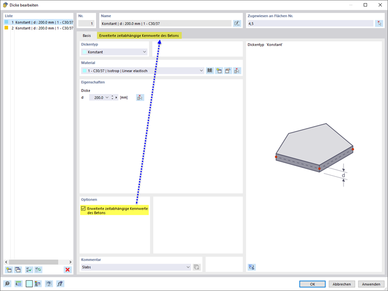
Once you activate the creep and/or shrinkage for the material, there is the option to define "Advanced Time-Dependent Properties of Concrete" in the dialog boxes for the cross-sections and thicknesses using this material. Select this check box and then define the parameters for the creep or shrinkage in the corresponding tab (see Image 02).
If you deactivate the creep and shrinkage in Cross-Sections and Thicknesses, it is not taken to the account for the structural components with these Cross-Sections and Thicknesses assigned. The settings made in Cross-Section or Thickness have dominance over those in the material.
Further information can be found in the chapter of the Concrete Design online manual at the link below.