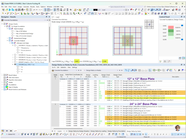
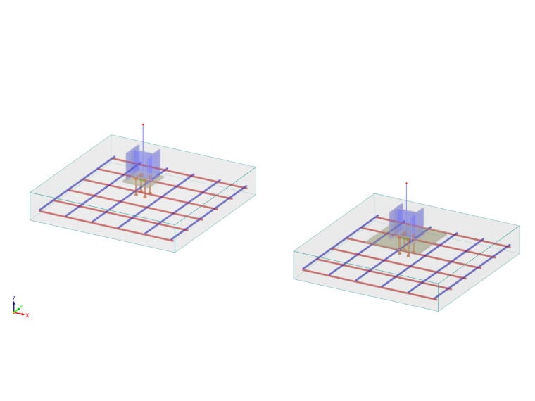
The Steel Joints and Concrete Foundations add-ons can be linked using the following workflow:
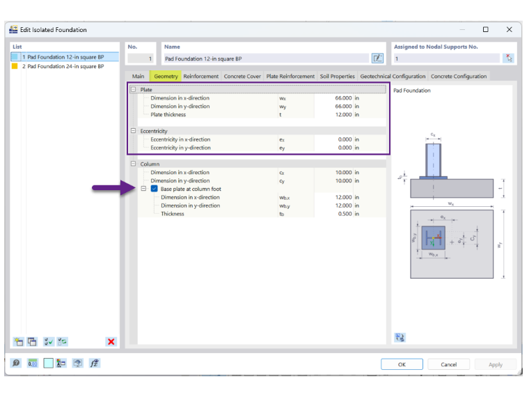
1. In the Concrete Foundations add-on, define the footing dimensions and eccentricities. If the base plate dimensions are already known, enable Base plate at column foot in order to enter the dimensions (Image 1).
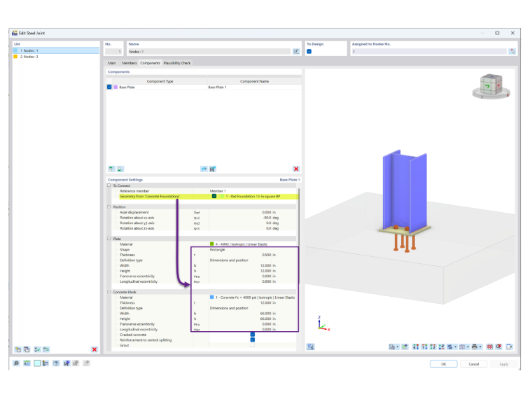
2. In the Steel Joints add-on, enable Geometry from Concrete Foundations in order to automatically transfer the base plate dimensions, footing dimensions/material, and eccentricities (Image 2).
3. After completing the base plate design, update the base plate dimensions in the Concrete Foundations add-on to keep both add-ons consistent.
When Base plate at column foot is enabled, the dimensions in the Steel Joints add-on are overridden by the values entered in the Concrete Foundations add-on.
In the Concrete Foundations add-on, the base plate dimensions define the loaded area used for the footing design. This influences both the flexural design and the two-way (punching) shear check (Image 3).
For the two-way shear check, the critical perimeter is located at a distance of d/2 from the loaded area. Increasing the base plate dimensions increases the length of the critical perimeter, reducing the applied punching shear stress.
For the flexural design, a larger base plate reduces the footing cantilever length, which can decrease the required bottom reinforcement.