The structural analysis software RFEM 6 is the basis of a modular software system. The main program RFEM 6 is used to define structures, materials, and loads of planar and spatial structural systems consisting of plates, walls, shells, and members. The program also allows you to create combined structures as well as to model solid and contact elements.
RSTAB 9 is a powerful analysis and design software for 3D beam, frame, or truss structure calculations, reflecting the current state of the art and helping structural engineers meet requirements in modern civil engineering.
Do you often spend too long calculating cross-sections? Dlubal Software and the RSECTION stand-alone program facilitate your work by determining section properties of various cross-sections and performing a subsequent stress analysis.
Do you always know where the wind is blowing from? From the direction of innovation, of course! With RWIND 2, you have a program at your side that uses a digital wind tunnel for the numerical simulation of wind flows. The program simulates these flows around any building geometry and determines the wind loads on the surfaces.
Are you looking for an overview of snow load zones, wind zones, and seismic zones? Then you are in the right place. Use the Geo-Zone Tool to determine quickly and efficiently snow loads, wind speeds, and seismic data according to ASCE 7‑16 and other international standards.
Would you like to try out the capabilities of the Dlubal Software programs? You have the opportunity to do so! The free 90-day full version allows you to thoroughly test all our programs.
Accuracy of RWIND Results and Ratio of Accuracy Versus Cost
The RWIND program was designed to quickly and easily calculate wind flow around buildings in order to obtain pressure values on their surfaces and generate load forces. In order to meet this main goal, a number of compromises had to be made, such as allowing the use of a simplified model or a relatively coarse computational mesh. It is obvious that these simplifications affect the accuracy of the results. Increasing the accuracy of the results using a finer mesh and other user settings in RWIND is possible, but this process may not be easy and requires sufficient experience with CFD simulations. An important question here is what is the acceptable ratio of effort and cost to the improvement in accuracy achieved. We recommend reading the CFD Project Accuracy vs. Effort article which deals with this issue in detail.
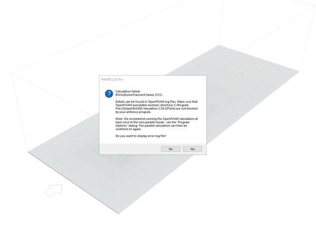
RWIND Error E315
When increasing the mesh density, memory and performance requirements do not grow linearly, but with the 3rd to 4th power (we have three spatial dimensions and also a reduction of the time step is necessary). This not only leads to a significant slowdown of the calculation, but also various problems can start to appear, which are usually related to the fact that the program approaches its limits or the limits of the hardware used. These problems also include error E315 which indicates a general failure inside the OpenFOAM© calculation modules – such as memory allocation failure, loss of numerical precision, and so on. The specific reasons for the failure can be different. More detailed information can be found from the relevant Log File.
RWIND Customer Support and its Limits
Dlubal customer support always tries to help RWIND users who encounter any problems. However, numerical simulations of wind flow can be very complex and results cannot generally be guaranteed. This is due to the fact that there is still no mathematical proof of the existence and uniqueness of the solution of the Navier-Stokes equations that describe this flow and which RWIND solves numerically using the finite volume method. Although the calculation converges to the correct solution in most cases, a failure of the calculation cannot be excluded. In the event that a calculation failure occurs in a large and complex project, assistance can be very time-consuming. If you are interested in additional extended assistance, please Contact Our Sales Team.
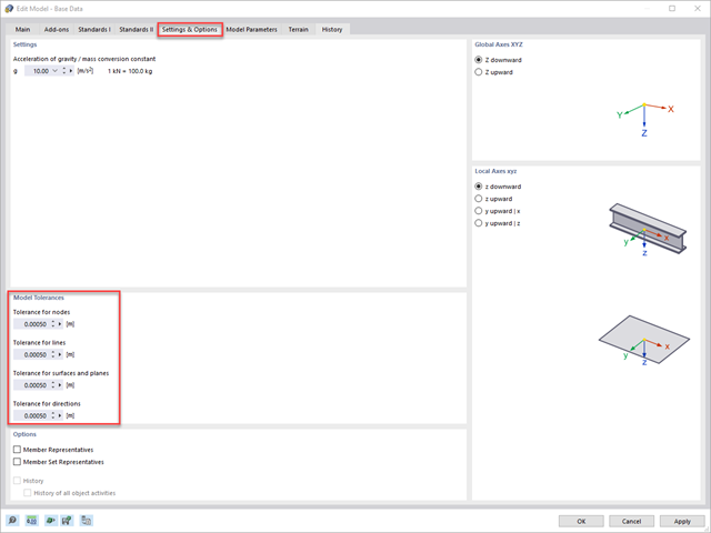
In order to avoid inconsistencies in a model caused by data imports from CAD programs or by modeling, RFEM 6 provides the option to define model tolerances for nodes, lines, surfaces, and directions in the input data. In this way, you can specify as of which tolerance are the nodes, lines, surfaces and distances to be considered as identical and combined together.
These model tolerances are taken into account in the program, on the one hand, when individual model parameters are modified using the "Move/Copy" function and, on the other hand, when the "Drag & Drop" function is used. However, if the position of the model parameters is defined using the table, the specified tolerances can be fallen short of at will. (Note: In the video, the model tolerance has been set a little coarser so that the effects of this setting become clear. Usually, a model tolerance of 0.0005 m is preset by the program.)
In RFEM 5, such inconsistencies in the model could be automatically eliminated using the "Regenerate Model" function.
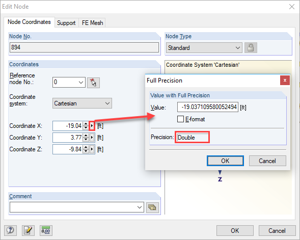
The problem is minimal inaccuracies in both models. If the support reactions are transferred from one model to another, they are exported as "free loads" with fixed coordinates. If the coordinates do not match 100%, it may happen in edge areas that the support reactions are not considered if the corresponding objects are located slightly shifted next to the surface. The geometric relations can be quickly checked by displaying the "Full Precision" for the nodes and loads (see Image 01 and Image 02).
It is often helpful to regenerate the model and to round the nodal coordinates to six decimal places, for example. This function can be accessed using the menu "Tools → Regenerate Model" (see Image 03).
Another solution would be to move the border lines of the surfaces into which the loads are to be imported a few millimeters from the outside. This ensures that all free loads are within the surfaces to be loaded.
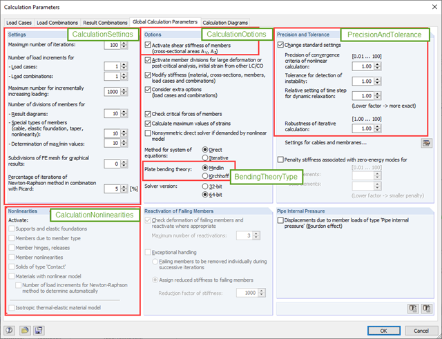
' get model interface Set iApp = iModel.GetApplication() iApp.LockLicense ' get calculation interface Dim iCalc As RFEM5.ICalculation2 Set iCalc = iModel.GetCalculation ' get surface bending theory Dim calc_bend As RFEM5.BendingTheoryType calc_bend = iCalc.GetBendingTheory ' get settings for nonlinearities Dim calc_nl As RFEM5.CalculationNonlinearities calc_nl = iCalc.GetNonlinearities ' get precision and tolerance settings Dim calc_prec As RFEM5.PrecisionAndTolerance calc_prec = iCalc.GetPrecisionAndTolerance ' get calculation settings Dim calc_sets As RFEM5.CalculationSettings calc_sets = iCalc.GetSettings ' get calculation options Dim calc_opts As RFEM5.CalculationOptions calc_opts = iCalc.GetOptions ' set ShearStiffness to false calc_opts.ShearStiffness = False iCalc.SetOptions calc_opts