Modeling Structure
The thermal break of the outer and inner sides is usually done using an insulating strip made of polystyrene hard foam. In the case of Schöck Isokorb®, tensile forces are absorbed by stainless steel and compressive forces by micro-fibre reinforced high performance concrete with PE-HD plastic coating through the insulating layer. The transfer of torsional moments through the insulating layer is therefore not possible. Depending on the selected type of Isokorb®, moments and/or shear forces can be transferred. This limited force transmission must be considered in the structural analysis.
Technical information according to EC 2 [1] for the Isokorb® includes an FEM guideline describing the modeling. The Schöck company recommends the following approach for the design of Schöck Isokorb® using the finite element method:
- Separate the external component from the supporting structure of the building.
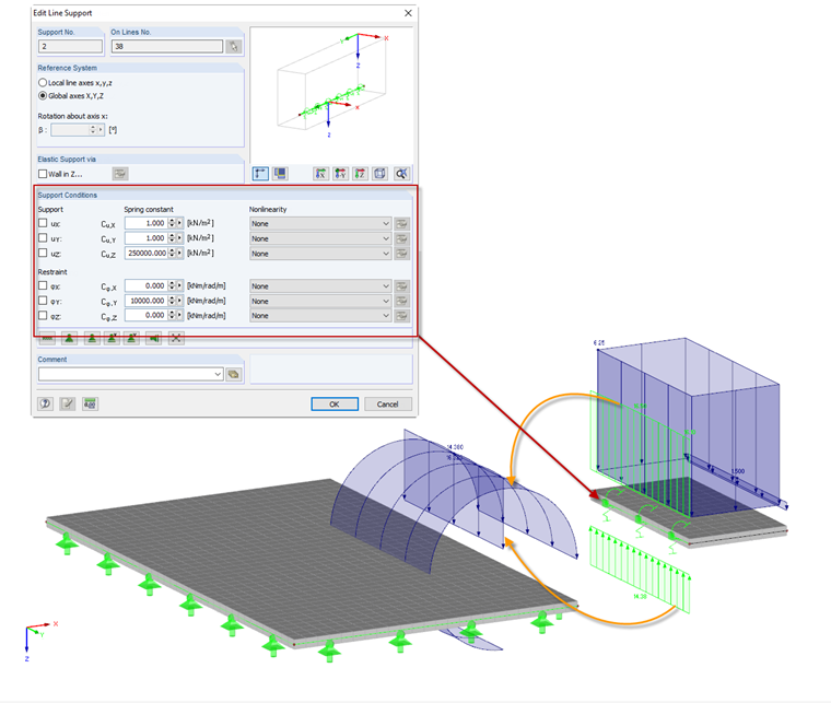
- Determine the internal forces on the external component support, taking into account the spring stiffness values (recommendation for Schöck Isokorb®). Recommended approximate spring values for Schöck Isokorb®:
10,000 kNm/rad/m for a rotational spring
250,000 kN/m² for a vertical spring - Select the Schöck Isokorb® type, including the determined design values for the shear force vEd and the moment mEd.
- Apply the calculated shear force vEd and the moments mEd as external edge loads to the load-bearing structure (ceiling slab, for example).
![Structural System for Schöck Isokorb® Type K from [1]](/en/webimage/009555/2419353/01-en-png.png?mw=760&hash=7ec548270c812e4679005b311ca774da4860d51a)
When separating the external component of the supporting structure of a building, the external component loads must be applied manually as additional edge loads on the supporting structure. As shown in Image 02, a balcony slab was modeled separately from the floor slab, and the support forces of the balcony slab were defined as an edge load of the floor slab.
Modeling in RFEM Using Line Hinge
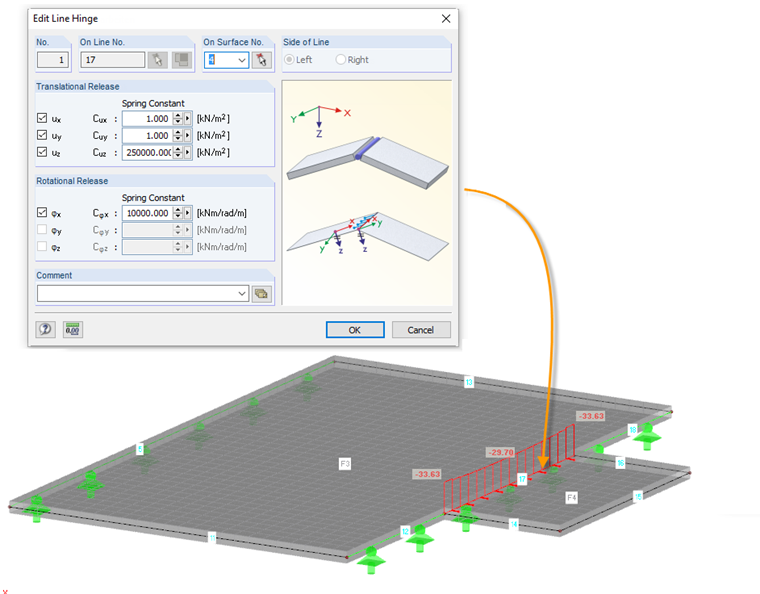
In order to avoid an additional effort of applying the edge loads from the external component, it is possible to model the external component together with the supporting structure in RFEM. Thus, the limited force transmission due to the Isokorb® is considered correctly in the FEM calculation, but a line hinge must be arranged at the intersection between the external and the internal component (installation location of Isokorb®). By defining the hinge properties, the specific effect can be considered in the force flow. The line hinge is arranged on the external side (balcony side) in this case. Please note it is not possible to define any nonlinearities for the hinge properties when using the line hinge. However, the line hinge is sufficient for the general application of Isokorb®, for example, in the case of a balcony cantilever slab where the moment and the shear force only act in one direction.
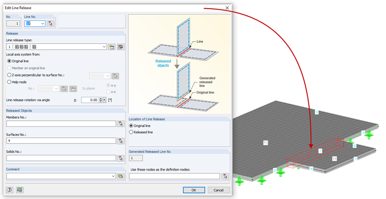
Modeling in RFEM Using Line Release
Depending on the selected Isokorb® type, the transferable forces are different. Thus, moments and shear forces can also be transmitted in only one direction, depending on the type. When defining nonlinear force transmission (for example a failure in one direction) on a connection line between the external and internal component, you can use a line release in RFEM. In the first step, it is necessary to define a line release type with the corresponding properties of the selected Isokorb®. In order to deactivate the spring effect in one direction, select the "Partial activity..." option under "Nonlinearity" and in the corresponding details, select the "Spring ineffectiveness" option in the respective direction. Image 04 shows the properties of Isokorb® type K with the option to transfer a force direction (tension) and a translational direction.
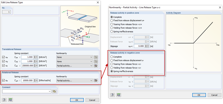
The line release type shown in Image 04 is defined as a line release on the connection line between the external and the internal components.
Result Evaluation
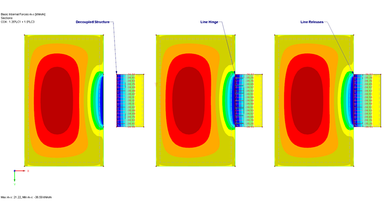
The Isokorb® design requires the transmission of the design internal forces. When modeling the components separately, as shown in Image 01, the supporting forces of the external component can be used. When using a line hinge or a line release for the modeling, it is possible to display the forces to be transmitted by using "Result Display on Sections". In this way, you can generate a section on the connection line (Isokorb®) and select the surface number of the external component for the result output. Image&bsp;06 shows a comparison of the plate bending moments mx resulting from the modeling methods described above. You can recognize a good agreement between the results of the individual modeling approaches here.