


At this point, it is also relevant to mention the previous technical article about RF-/FOUNDATION Pro, which describes the determination of the ground failure resistance according to EN 1997‑1, Annex D. The following article will focus on determining the average soil parameters when applying a soil profile with different soil layers.
Considering Ground Water Level
When entering a soil profile in RF-/FOUNDATION Pro, there is an option to consider the ground water level.
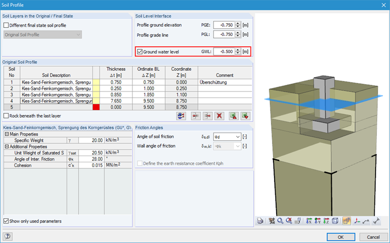
As you can see in Image 01, the ground water level of 0.50 m has been defined above the foundation's upper edge.
Basically, it can be stated that entering ground water level—depending on the elevation—has an effect on all designs. The reason is that ground water is considered a "load" (buoyancy) on the action side and on the resistance side in the soil parameters.
In the following text, the uplift limit state, the ground failure resistance, and the sliding resistance designs are described with regard to the influence of the ground water level on an example. In this case, "drained subsoil conditions" are preset in Window 1.1. This has an impact on the formulas for determining the ground failure and sliding resistance.
Uplift Limit State Design
The design of buoyancy safety is performed in RF-/FOUNDATION Pro under the "uplift" designation. The foundation's uplift due to the hydrostatic uplift force of the water is actually a static equilibrium analysis in terms of the uplift limit state UPL. Safety against uplift of a non-anchored structure is achieved if the following condition is met:
Gdst,k ∙ γG,dst + Qdst,rep ∙ γQ,dst ≤ Gstb,k ∙ γG,stb + Tk ∙ γG,stb
During the uplift stability design of a foundation, it is checked whether the lifting vertical loads are absorbed or compensated for by the self-weight of the foundation. In RF-/FOUNDATION Pro, the lifting vertical loads are composed of the hydrostatic buoyancy of the foundation lying under the ground water level as well as of any lifting loads that may be present.
The component Tk describes an additional characteristic shear force Tk = ηz ∙ Eah,k ∙ tan δa, which is applied as a stabilizing effect, as a friction force directly on a structural wall (lateral surfaces of the foundation block). Tk is conservatively not applied in RF-/FOUNDATION Pro. According to [1] and [2], the design of permanent structures in BS-A should be performed without applying shear forces.
If the bottom edge of the foundation is below the ground water level, it is necessary to determine the hydrostatic uplift force for the buoyancy verification.
In RF-/FOUNDATION Pro, the resulting vertical lifting force arises from the hydrostatic uplift force and, if applicable, from the existing lifting loads to Vres, neg, and can be found in Window 2.2 under the design details of the uplift limit state design.
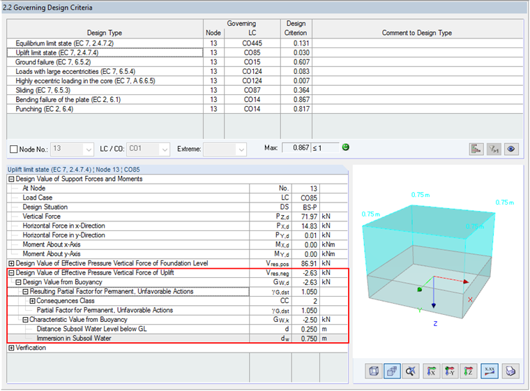
Note on bucket foundation: In the case of bucket foundations, the volume of the actual bucket is taken into account when determining the uplift force. This means that the positively acting component of the water pressure on the foundation upper edge is reduced accordingly about the base area of the bucket dimensions.
When determining the resulting, positively acting vertical force in the soil joint, the position of the ground water level is now taken into account when applying the earth covering. This means that the soil layer above the foundation's upper edge must be subdivided with regard to the ground water level elevation, and the positive vertical load is determined from the weight of the earth covering with the effective weight, taking into account the buoyancy.
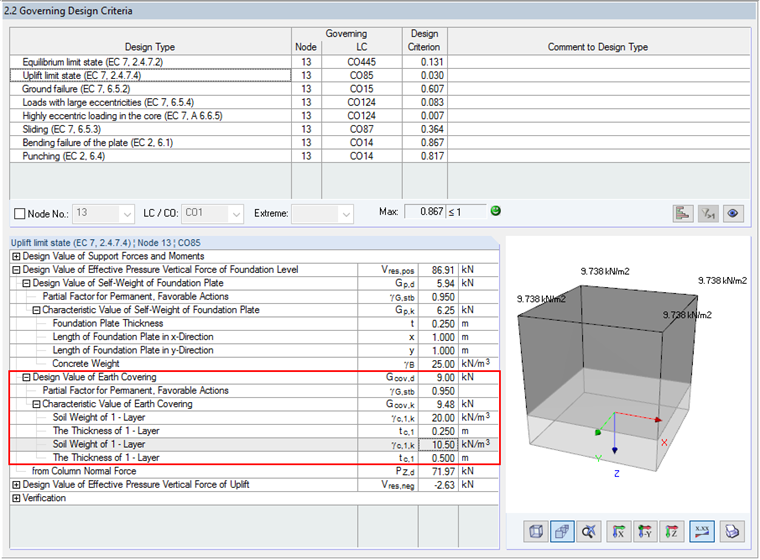
If a foundation plate with a height of 0.75 m is overloaded and the ground water level of 0.50 m above the foundation's upper edge is set, the earth covering should be divided into two layers with different weights. The layer resting entirely within the ground water must be taken into account with the weight of the saturated soil, minus the buoyancy. RF-/FOUNDATION Pro displays the detailed values per soil layer in the result window 2.2.
In this case (see Image 03), a weight of γ = 20.00 kN/m³ applies above the ground water level. For the soil layer within the ground water, the saturated soil weight γsat = 20.5 kN/m² minus the ground water weight of 10.00 kN/m³ is taken into account, resulting in a weight density under lift γ' = 10.5 kN/m³. To determine the design value of the load due to earth covering, the partial factor γG,stb is applied.
In this case, the column dimensions of the connected columns must again be considered, as is the case of the bucket foundation when applying the positive water pressure. The uplift stability design is fulfilled if Vres,neg ≤ Vres,pos.
Ground Failure Resistance Design
Security against ground failure (GEO-2) is achieved if the condition Vd ≤ Rd is satisfied. The influence of the ground water must be taken into account on the action side and on the resistance side.
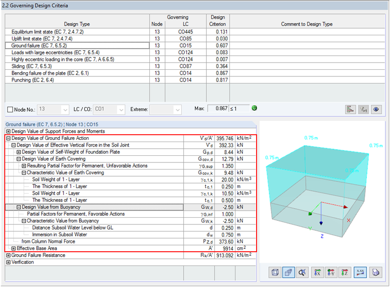
Similarly to the uplift stability design, it is also necessary to consider the ground weight density of the soil under uplift (submerged weight). In contrast to the uplift stability design, the design value of the load due to the earth covering is determined using the partial safety factor γG,sup for permanent, unfavorable actions. The design value from buoyancy is taken into account with the partial safety factor γG,inf.
The ground failure resistance is determined in RF-/FOUNDATION Pro according to EN 1997‑1, Annex D. The characteristic value of the ground failure resistance can be calculated according to [1] Annex D, Equation (D.2), as follows:
Note to Equation (D.2) above: According to Annex D of [1], the parameter γ' corresponds to the "design effective weight density of the soil below the foundation level".
On one hand, the effective weight density γ' is taken into account when determining the effective overburden pressure at the level of the foundation base. On the other hand, the effective weight density γ' is also applied to the soils below the foundation level and thus directly applied to the determination of the ground failure resistance. Furthermore, the lower surcharge due to the applied buoyancy also has a negative impact on the determination of the eccentricities ex and ey. The eccentricities become larger, thus the failure is smaller for the computational foundation base A'.
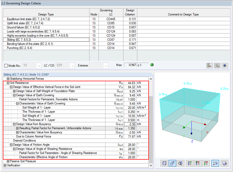
Sliding Resistance Design
Safety against sliding (GEO-2) is achieved if the condition Hd ≤ Rd + Rp,d is met.
In the case of the sliding resistance design, the ground water level is only considered on the resistance side. On the action side, the ground water level is not taken into account. The horizontal force Hd, for which the sliding resistance of the foundation is to be checked, consists of the support forces calculated in RFEM or RSTAB. The resulting Hd covers all design-relevant actions in the foundation base, including the active earth forces. At this point, it should be pointed out that the active earth pressure is not considered automatically in RF-/FOUNDATION Pro. If the horizontal component of the active earth pressure is to be taken into account in the design, this should be entered as an "additional concentrated load" in P-x or P-y in Window 1.4 Loading.
When determining the resistance, the ground water level is considered by using the effective weight density γ' and as the uplift load itself. The effective weight density γ' has an influence on the resulting vertical load Gcov,d of the earth covering. The buoyancy resulting from the ground water level above the foundation's base is also applied as an unfavorable action with the partial safety factor γG,sup, whereby the resulting favorable vertical load V'd is reduced for the sliding resistance design.
If the favorable passive earth pressure Rp,d is to be considered in the calculation according to [1] Annex C, it is necessary to activate this option in Window 1.1 under "Settings for Sliding". If this is the case, the effective weight density γ' applies for the determination of the earth resistance.