


Furthermore, you can use different copy functions and parameterized input options. However, this procedure normally requires considerable effort. It is more convenient to model such structures using prefabricated catalog elements provided by the Block Manager. These elements are automatically stored in the database during program installation. Thus, you can use tower segments, platforms, antenna brackets, cable ducts, and so on as parameterized building blocks for generating diverse tower structures.
Specific options to model and design tower buildings are available in the RF-/TOWER add-on modules. But this article describes the modeling of a simple lattice tower with parameterized catalog elements of the Block Manager. The tower consists of two segments and a platform.
Block Manager
You can open the Block Manager on the "File" → "Block Manager" menu or by clicking the corresponding menu button. The Manager includes various catalog elements, making the modeling of member and surface objects easy.
.png?mw=760&hash=38425bb54c87cd81e22f37b2162e48a4f6b92a6c)
Tower Segment – Bottom
The following catalog category is to be defined for the construction in the bottom area of the tower:
"Towers" → "Mast - Segments" → "Rectangular".
Then, you can select type TSR038 in the list on the right.
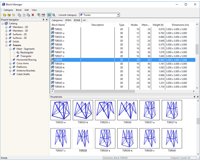
Double-clicking on this block type opens the "Insert Block" dialog box.
.png?mw=760&hash=ebfad9f5d8dad47a559fffdaa3c3ba76956d9f97)
Lattice towers generally consist of angle profiles. The preset cross-sections and the material can be adjusted as required (clicking a cross-section row displays its use in the block graphically). For this example, however, the cross-sections are not modified.
The height of the segment is to be changed to 5.50 m. The adjustment of this parameter is dynamically updated in the graphic.
A base point of the segment is appropriate for the "Insert Point of Block"; for example, Node 6. The number of the node can be selected in the list or defined graphically by clicking the base point. [OK] transfers the model to RFEM/RSTAB.
Platform
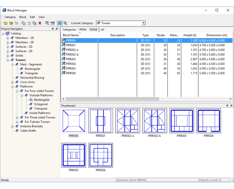
To select the platform, the Block Manager must be reopened. The following catalog category is to be specified:
"Towers" → "Platforms" → "For Four-Sided Towers" → "Outside Platforms" → "Rectangular"
Then, you can choose type PRR000 to the right.
.png?mw=760&hash=bceda5d3008f02dc28b87726a8388dee4e7edd05)
In the dialog box, platform parameters a and b must each be reduced to 2.00 m in order to adapt them to the upper dimensions of the previously set segment (see Image 03). Alternatively, it is possible to take the distances from RFEM/RSTAB by using the […] button that appears when activating the input text box.
The "Global Position of Reference Point" is to be modified to Node 1. The number of the node on which the platform should be inserted can be selected in the list or determined graphically in the tower model using the [Select] button. The platform will be transferred to RFEM/RSTAB by clicking [OK].
Tower Segment – Top
Again, the upper part of the tower structure is created with the Block Manager:
"Towers" → "Mast - Segments" → "Rectangular"
Type TSR035c is to be selected.
.png?mw=760&hash=652120ab44efa59bac23c58e6232ba990d6d7b51)
.png?mw=760&hash=835a3b4294e8d6e473e4e038ce805f9ef0fd224f)
Node 2 is to be specified as the "Insert Point of Block". This can be done graphically by clicking the base point in the front.
Again, the "Global Position of Reference Point" is to be set to Node 1 of the RFEM/RSTAB model.
The height h must be changed to 4.00 m, the lower distances a2 and b2 to 2.00 m, and the upper distances a1 and b1 to 1.00 m.
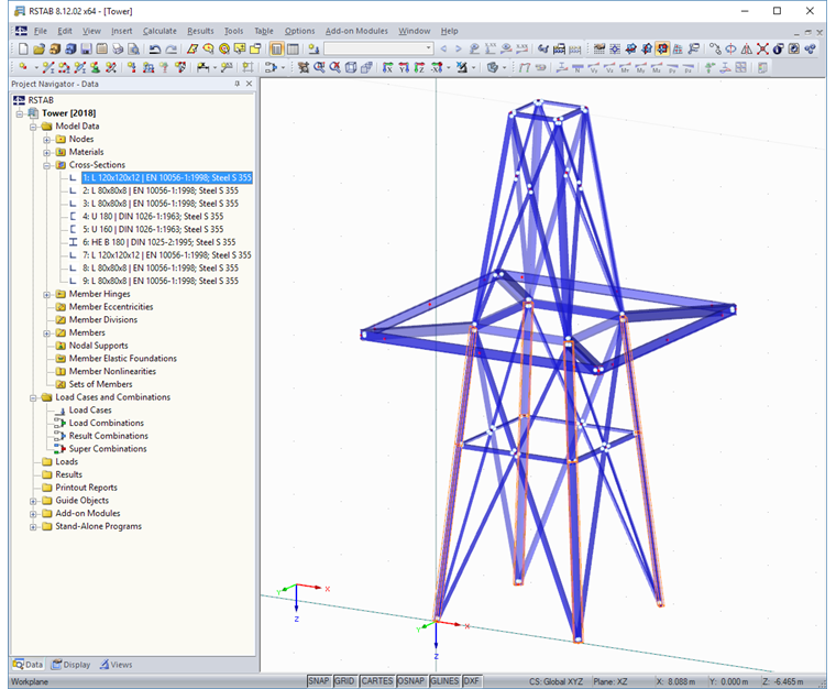
After clicking [OK], the tower model looks as shown in Image 08.
It is possible that nodes with identical coordinates will be created when combining the blocks. To clean the model, a corresponding check should be carried out.
"Tools" → "Model Check" → "Identical Nodes"
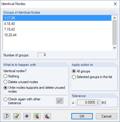
Nodes lying upon one another are shown in the "Identical Nodes" dialog box. It is also possible to unite them there.
Finally, the tower model can be extended by other catalog elements such as antenna brackets, cable ducts, cross beams, or bracings. These building blocks are stored with parameters, too.
Conclusion
Lattice towers can be modeled easily by means of parameterized catalog elements of the Block Manager. The library of the system components is also extendable by user-defined specifications so that variations of recurring models can be created quickly, using blocks.
Alternatively, you can use the possibilities offered by the various RF-/TOWER add-on modules developed for the planning and design of towers. They also allow you to determine specific requirements of load application. The RF-/TOWER modules are presented in a webinar.