


General
Calculating structures as 3D models is the general practice in modern structural analysis and design. This takes into consideration many variable loads such as wind, snow, imposed loads, and possibly alternative moving loads. This generates a large number of load combinations, which also have to be considered for the stability analysis of a steel column.
The following example compares the results of the "Bending and compression" stability analysis according to EN 1993-1-1, Section 6.3.3, with regard to the internal forces from load combinations and an enveloping result combination. The different options available in the RF-/STEEL EC3 add-on module will be explained.
Model and Loading
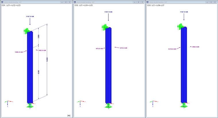
A corner column of a steel hall will be designed. The hinged column has a height of 10.85 m and receives horizontal loads from connected trusses at a height of 8.20 m. Only three load combinations from seven load cases and one result combination will be considered.
The original structural model has more than 340 load combinations for the ultimate limit state. Not all of the seven load cases will be listed separately. They were determined as governing from the entire structural analysis and are contained in the attached example file. To simplify, partial safety factors and combination factors have been deliberately omitted. The loads have to be considered as design loads.
- Cross-section:
- 2IK HEM 800 + HE M 800 | - + DIN 1025-4:1994
- Material:
- Structural steel S 355 | DIN EN 1993-1-1:2010-12
- Load combinations:
- CO1 = LC1 + LC2 + LC3
- CO2 = LC1 + LC4 + LC5
- CO3 = LC1 + LC6 + LC7
- Result combination:
- RC1 = CO1/s or CO2/s or CO3/s
Stability Analysis with Load Combinations
Image 02 shows the internal forces N, My, and Mz of CO2. According to EN 1993-1-1, Section 6.3.3, Equation 6.6.2, these three internal forces result in the maximum design ratio of 92%. Interaction factors are used in this stability analysis on the equivalent member. According to [1], Section 6.2.2 (2), Note 1, the interaction formulas are based on the model of a single-span beam with lateral and torsional restraints, with or without intermediate support, which is subjected to compression forces, boundary moments, and/or lateral loads. By applying Table A.2 of [1], the actual moment distribution is taken into account when determining the interaction factors.
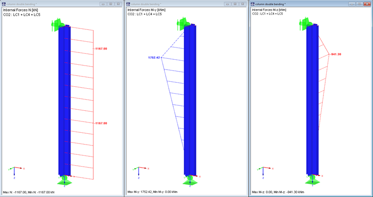
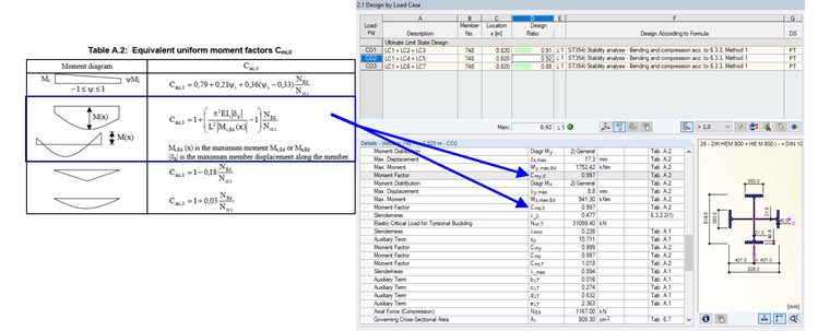
Image 03 shows how the moment distribution for My and Mz of CO2 is classified in RF- STEEL EC3 and the equivalent moment factors Cmi,0 are determined according to Table A.2 of [1].
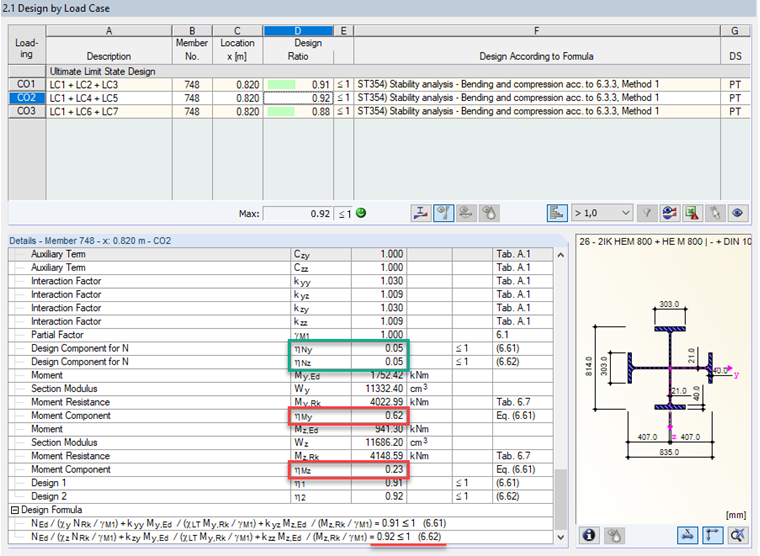
Looking at the detailed result evaluation for the stability analysis in Image 04, it is clearly evident that the axial force barely plays a role, and the bending moments are decisive for the maximum design ratio.
Stability Analysis with Result Combination (Envelope)
To save time during the calculation, you can set the type of calculation for result combinations of the type OR to the second option in the "General" tab at "Details" in RF-/STEEL EC3 during the design phase. It should be clarified here that the enveloping internal forces are used for performing the stability analysis when this option is selected. Image 05 shows the governing max/min results for Result Combination 1.
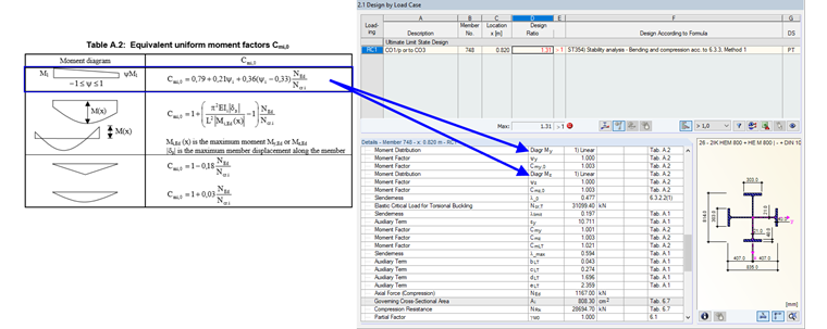
Another important point is the determination of interaction factors. Since the moment distribution of an enveloping result combination represents a maximum or minimum value for each x-location, no real moment distribution can be expected here. Therefore, a linear moment distribution with ψ = 1 will be used. See also Image 06.
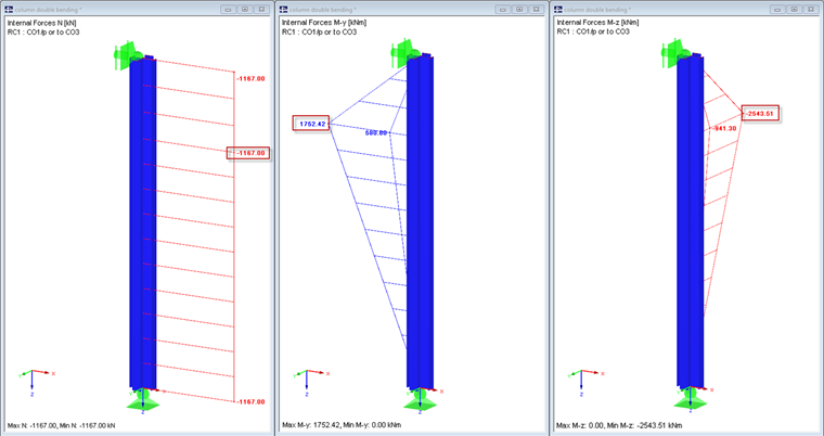
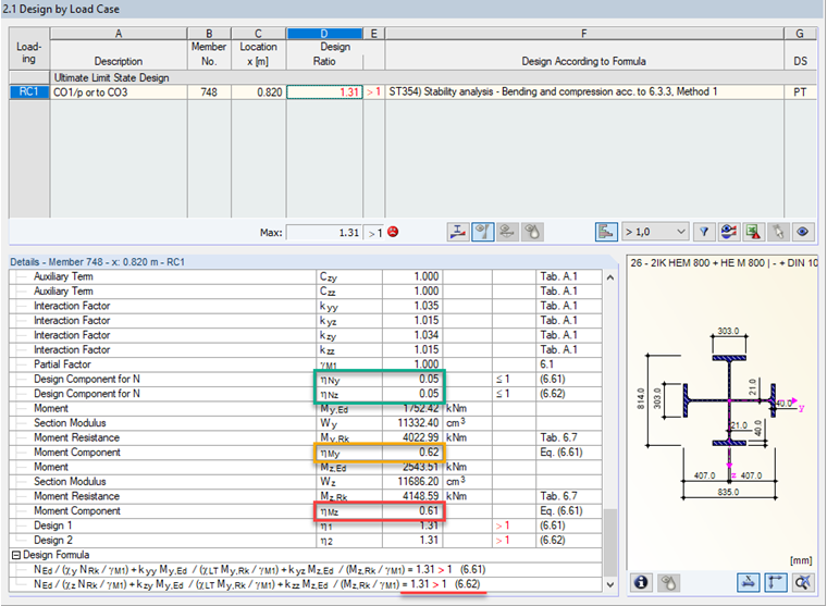
The detailed result evaluation of the stability analysis for Result Combination 1 as an envelope shows one obvious disadvantage of this method. Since the absolute extreme values are assumed for the bending moments and not the corresponding moments, this result falls well within the safe range. The maximum My = 1,752.42 kNm belongs to CO2 and the minimum Mz = -2,543.51 kNm belongs to CO3. The conservative solution with the envelope results in a ratio of 131%.
Stability Analysis with Result Combination (Default)
If you set the type of calculation for result combinations of the type OR to the first option, which is also the default setting, at "Details" in the "General" tab of RF-/STEEL EC3, the results are comparable to those of the individual LCs.
Conclusion
The example shown here is a practical example with the aim of explaining the options for a quick calculation, as well as the limitations when using enveloping results.