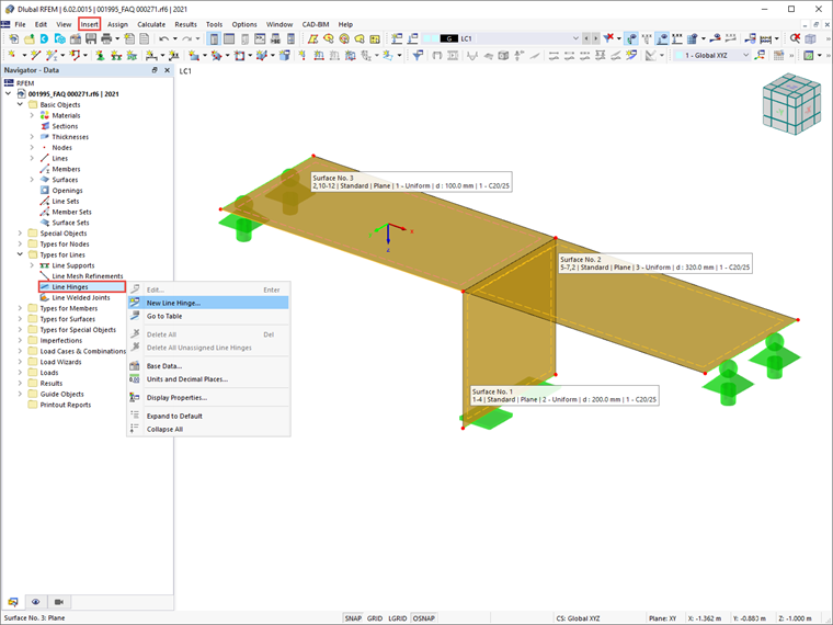
Defining Line Hinges
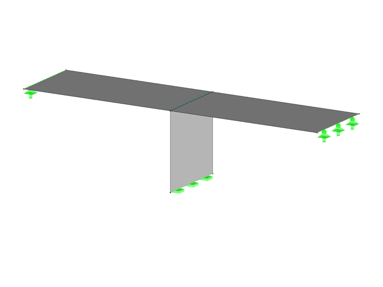
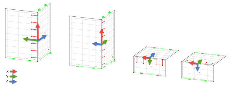
In RFEM 6, line hinges can be defined using the “Insert” menu. They are also available as “Types for Lines” in the Data navigator (Image 1). The way to define them will be described for the connection of the structure shown in Image 1.
To define a line hinge for surfaces that touch each other on one line, it is necessary to assign the hinge to both a line and a surface (as will be shown later). A line hinge can be defined on any boundary line of the surface, but not on a line integrated into the surface, as was the case in RFEM 5.
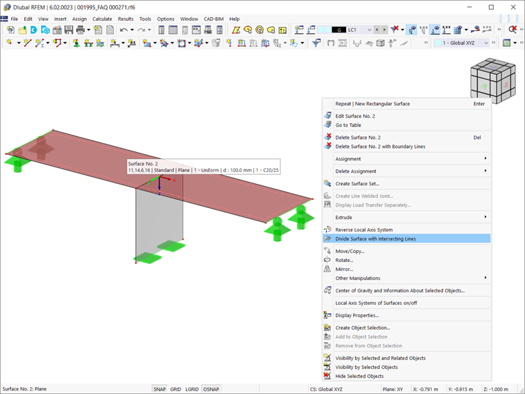
To do this in RFEM 6, you must first divide the surface with an intersection line in order to convert a line integrated into the surface into a boundary line. This can be done with the help of the “Divide Surface with Intersecting Lines” function (Image 2). Hence, if there is only one surface instead of two separate surfaces (that is, only Surface No. 2 in Image 2), you must use the above-mentioned option to divide it and obtain two separate surfaces, as is the case with Surface No. 2 and Surface No. 3 in Image 1.
Hinge Conditions
Defining line hinges means, in fact, controlling their degrees of freedom. The “Main” tab of the “New Line Hinge” window controls these basic parameters, known as “Hinge Conditions”. In contrast to supports, the degree of freedom for line hinges is activated by checking the box (for supports, the degree of freedom is then unchecked). The degrees of freedom for the line hinges are divided into three translational and one rotational degree. The former describes the displacements in the direction of the local axes, whereas the latter describes the rotation about the longitudinal line axis.
Thus, to define a hinge, you must first tick the check box for the respective axis. Then, you can set the constant of the translational or rotational spring to zero, but you can also adjust the “Spring constant” in order to model an elastic hinge.
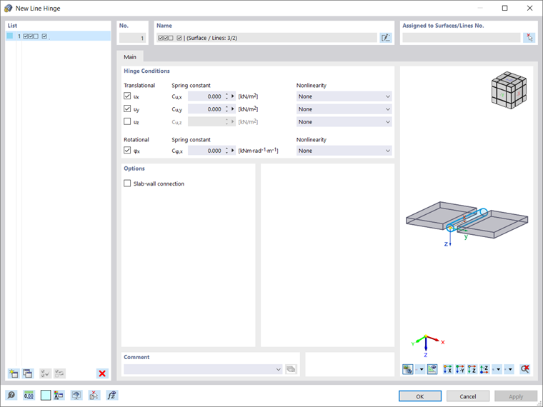
Please be aware that the release definitions of the line hinge do not refer to the internal forces within the surface, but to the local coordinate system of the line hinge. The degrees of freedom are based on the following axis definition: the x-axis points in the direction of the line, the y-axis is the tangent to the surface plane, and the z-axis is the normal to the surface. Hence, the degree of freedom ux reduces the force transmission along the surface edge and φx corresponds to a hinge joint.
In the “Nonlinearity” column (Image 5) of the “New Line Hinge” dialog box, you can specifically control the transfer of internal forces and moments for each component. Although in this example “None” is selected, the available options in the list of nonlinearities are: “Fixed if negative/positive n/mx” (that is, you can control whether the hinged effect is only given for positive/negative forces or moments); “Partial Activity” (that is, you can define yourself the type and parameters for the negative and positive zones); and “Diagram” (that is, you can define the number of definition points for the work diagram by entering the corresponding values).
For a φx-hinge with nonlinear properties, you can also define a Force/Moment Diagram (that is, you can define the definition points by defining values for the force and the corresponding maximum and minimum moments).
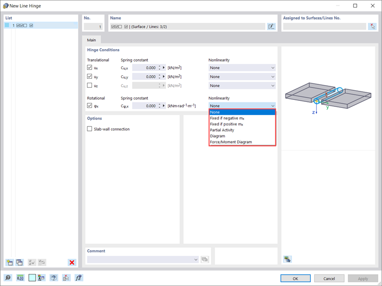
In the “New Line Hinge” dialog box (Image 3 and Image 5) you can also see the option called “Slab-wall connection” (available in the “Options” section). You can activate this option for slab-wall connections in masonry structures. This way, you can manage the parameters of the line hinge in order to limit the transmission of moments.
This is necessary due to the fact that in the case of slab-wall connections in masonry structures, moments are not transferred indefinitely, but only depending on the axial forces. Given that this option is not relevant for the example in this article, it will be discussed in more detail in an upcoming Knowledge Base article on the specific topic.
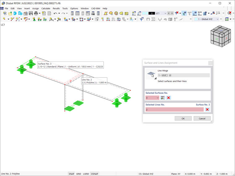
Once all parameters of the line hinge have been defined, it is necessary to assign the hinge to both a line and a surface. In this example, these are Surface No. 3 and Line No. 2. You can do this using the “Select Surfaces/Lines” icon in the upper right corner of the “New Line Hinge” dialog box; simply select the surface and line of interest as shown in Image 6.
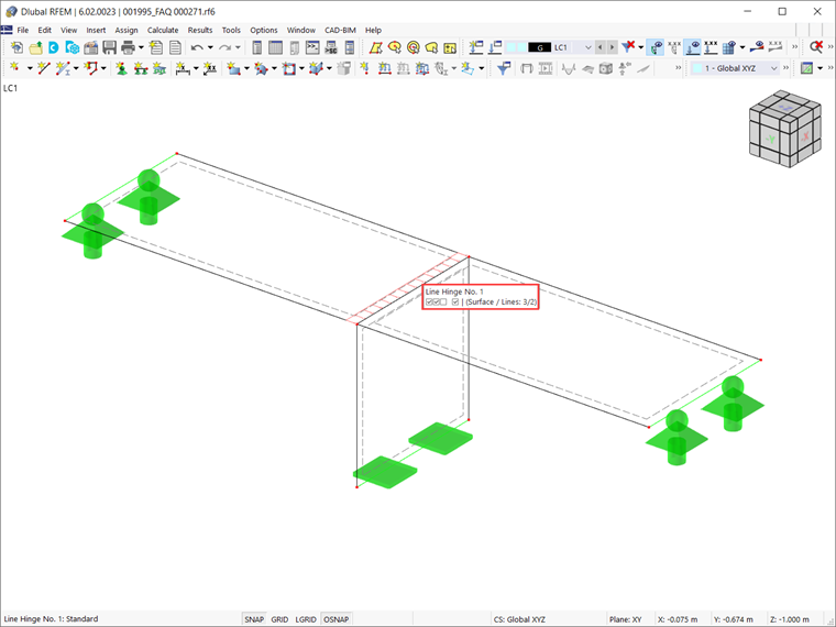
The line hinge generated in this way is finally available in the RFEM 6 working window, as shown in Image 7.
Summary
Line hinges allow you to consider correctly the connection between surfaces that touch each other on one line. This consideration is based on the possibility to control certain degrees of freedom, thus limiting the transmission of internal forces and moments.
In this manner, it is possible to consider entire decoupling of surfaces or elastic couplings by means of linear springs. In concrete construction, line hinges can be used to define an assembly gap. In timber construction, modeling with line hinges is necessary due to the very limited rotation transmission of forces.