The Aluminum Design Manual 2020 (ADM 2020) [1] provides essential guidance and design requirements for engineers and designers working with aluminum in structural applications. The ADM 2020 [1] provides methods to calculate the elastic LTB moment (Me). It outlines which equations should be used and followed, ensuring that aluminum structures are safe from this form of instability.
RFEM 6 references the type of section and internal forces calculated in the static analysis, and the Aluminum Design add-on applies these results to the equations from the ADM 2020 [1]. More specifically, the equations from Sec. F.4 [1] for LTB design. There are sub-sections within Sec. F.4 [1] used to classify the cross section of a member and calculate the LTB slenderness (λ). If more than one section applies, any applicable section shall be used.
Classification of Sections in LTB Design
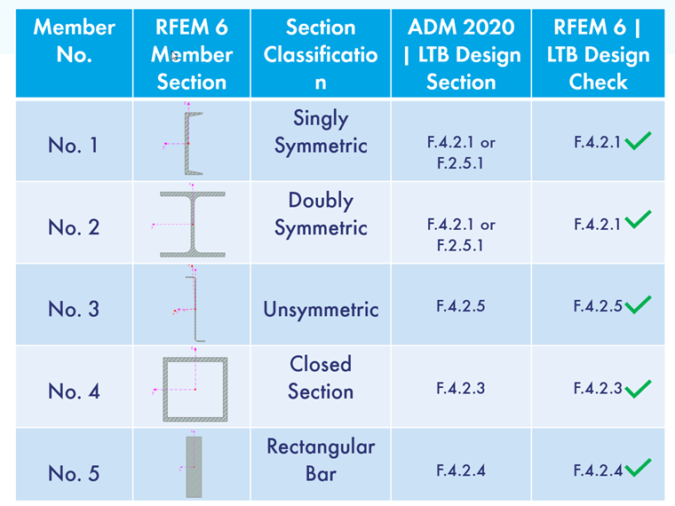
Sec. F.4 [1] classifies aluminum cross sections based on whether they are symmetric or unsymmetric about the bending axis, closed, or rectangular bar sections. In the upcoming sections of this article, there will be a variety of cross sections with an explanation of where they fall under Sec. F.4 [1]. This is then followed by how they are designed in RFEM 6. A simple comparison will be made between the ADM 2020 [1] and RFEM 6. In the image below, each example shows the correct code check and compares this with the code check used in RFEM 6.
Singly Symmetric Sections
A singly symmetric cross section is a section that can be perfectly mirrored about its bending or non-bending axis. Examples of singly symmetric standardized sections consist of T and Channel sections.
The slenderness for these types of shapes should be determined according to Sec. F.4.2.1 [1] which is for shapes symmetric about the bending Axis. If the section is unsymmetric about the bending axis, then it should be checked according to Sec. F.4.2.5 [1].
In the attached RFEM 6 model, a Channel section is modeled (Member No. 1) as a simply supported beam with uniform loading. Cross sections that are symmetric about the bending axis are designed according to Sec. F.4.2.1 [1] utilizing the Aluminum Design add-on.
Doubly Symmetric Sections
A doubly symmetric cross section is a section that can be mirrored perfectly about its bending and non-bending axis. Examples of standardized sections that are doubly symmetric consist of I sections, rectangular, and circular hollow sections.
LTB for a standardized I section should be designed according to Sec. F.4.2.1 [1], but can also be designed according to Sec. F.4.2.5 [1] since it can be symmetric or unsymmetric about its bending axis if lateral loading is applied.
In the attached RFEM 6 model, a doubly symmetric I-section is modeled (Member No. 4) as a simply supported beam with a uniform lateral load applied to it. This type of section is designed according to Sec. F.4.2.1 [1], because if we assume lateral loading in either primary axis direction, it is always symmetric about the bending axis.
Unsymmetric Sections
An unsymmetric cross section is a section that cannot be mirrored perfectly about either its bending or non-bending axis. An example of a standardized section that is considered unsymmetric about either of its axis is a Z-Section.
LTB for this section should only be calculated using Sec. F.4.2.5 [1] Any Shape. With this section, the slenderness value and elastic LTB is determined for unsymmetric sections.
In the attached RFEM 6 model, a Z-Section (CF 4ZU1.25x075) is modeled (Member No. 5) as a simply supported beam with a uniform load. In the Aluminum Design add-on, this shape is designed according to Sec. F.4.2.5 [1] with respect to LTB.
Closed Sections
A closed cross section refers to a structural shape where the perimeter of the section is completely enclosed. One common example of a closed section for an aluminum member is a rectangular tube or hollow rectangular section. In this case, the cross-sectional shape resembles a rectangle, but it is enclosed on all sides, creating a tube-like structure.
Calculating LTB for a closed section, the slenderness should be determined by referencing Sec. F.4.2.3 [1] Closed Shapes.
In the attached RFEM 6 model, a square hollow section is modeled (Member No. 6) as a simply supported beam with a uniform applied to it. Designing it according to the ADM 2020 in the Aluminum Design add-on, LTB is calculated utilizing Sec. F.4.2.3 [1] Closed Sections for determining the Slenderness Ratio (λ).
Rectangular Bars
A flat rectangular bar section refers to a geometric shape that is long and narrow with a flat surface and rectangular sides.
Sec. F.4.2.4 [1] should be used to calculate the Slenderness of a flat rectangular bar to ultimately find the critical buckling moment.
In the attached RFEM 6 model, a rectangular bar is modeled (Member No. 7) as a simply supported beam with a lateral uniform load. It is calculated utilizing the equations from Sec. F.4 [1] and the slenderness is calculated using Eq. F.4-7 under Sec. F.4.2.4 [1].
Conclusion
Calculating LTB according to ADM 2020 Sec. F.4 [1] requires an engineer to determine which sub-section their cross section falls under for determining the slenderness and other section properties. The main categories for this are divided by shape and symmetry. Whether it is symmetric or unsymmetric about the bending axis, if the section is closed/open, or if it is a rectangular bar.
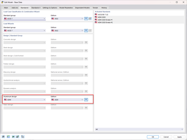
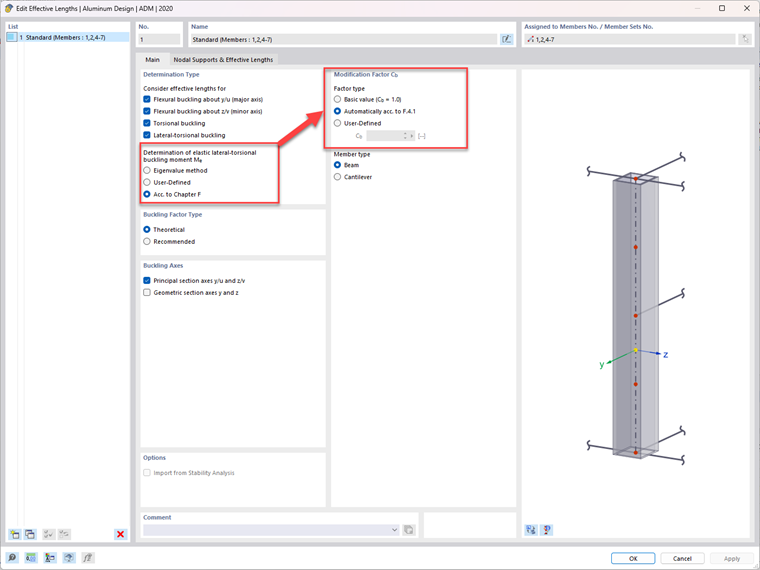
In RFEM 6, the Aluminum Design add-on classifies cross sections the same way as outlined in Sec. F.4 [1]. The ADM 2020 design standard must be chosen under the Standard I tab within the Base Data. Lastly, under the Effective Lengths in the Design Parameters of a member, Chapter F. must be selected. Lastly, under the same parameters, the Modification Factor (Cb) can be calculated according to Sec. F.4.1.