


RC structures require both global and local stability checks. While most modern software are capable to perform these analyses, the method of verification and the level of calculation transparency vary significantly. Below is a brief overview of typical stability verification, followed by a comparison of ETABS and RFEM 6.
Global Stability
Global stability is generally considered by including the P–Δ effect during structural analysis, after reducing the stiffness of structural elements to account for cracking effects.
According to ACI 318, commonly used stiffness reduction factors are:
| 0.70 | columns |
| 0.35 | beams |
| 0.25 | slabs |
For global stability analysis, stiffness reduction due to creep is often assumed as zero, since lateral loads are typically short-duration loads.
Local Stability
After completing the global analysis, local stability must still be verified, particularly for columns. In ACI 318, this is addressed using the Moment Magnification Method, through the βdns factor, which mainly depends on the internal forces acting on the column and the effective flexural stiffness (EI) of the element.
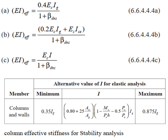
ACI 318-19 (6.6.4.4.4) proposes three approaches to estimate the effective cracked stiffness:
- Method a) only the concrete section is considered
- Method b) both, the concrete and the reinforcement are considered
- Method c) reinforcement and applied load are considered
In all methods, the effect of creep on stiffness is taken into account through the coefficient βdns.
Example
In the following the calculation results from ETABS and RFEM 6 are compared using a simple model of a reinforced concrete column.
Parameters
| Column section | 1.0 m × 1.0 m |
| Length | 8.5 m (X direction: fixed–free ends, Y direction: fixed–pinned) |
| Concrete strength | f'c = 40 MPa |
| Reinforcement ratio | 1% |
| Axial load | 10,000 kN |
| Moment around X | 3000 kNm |
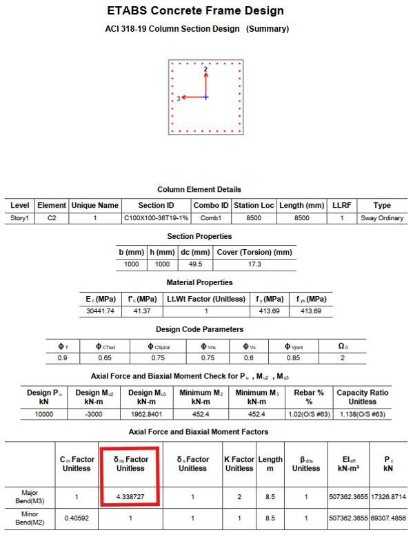
ETABS Results
→ method a) is internally used for column design
acc. to the results:
- dns = 4.33 → significantly larger than the ACI limit of 1.4
- the column is considered unsafe
- capacity ratio is 1.14
RFEM Results
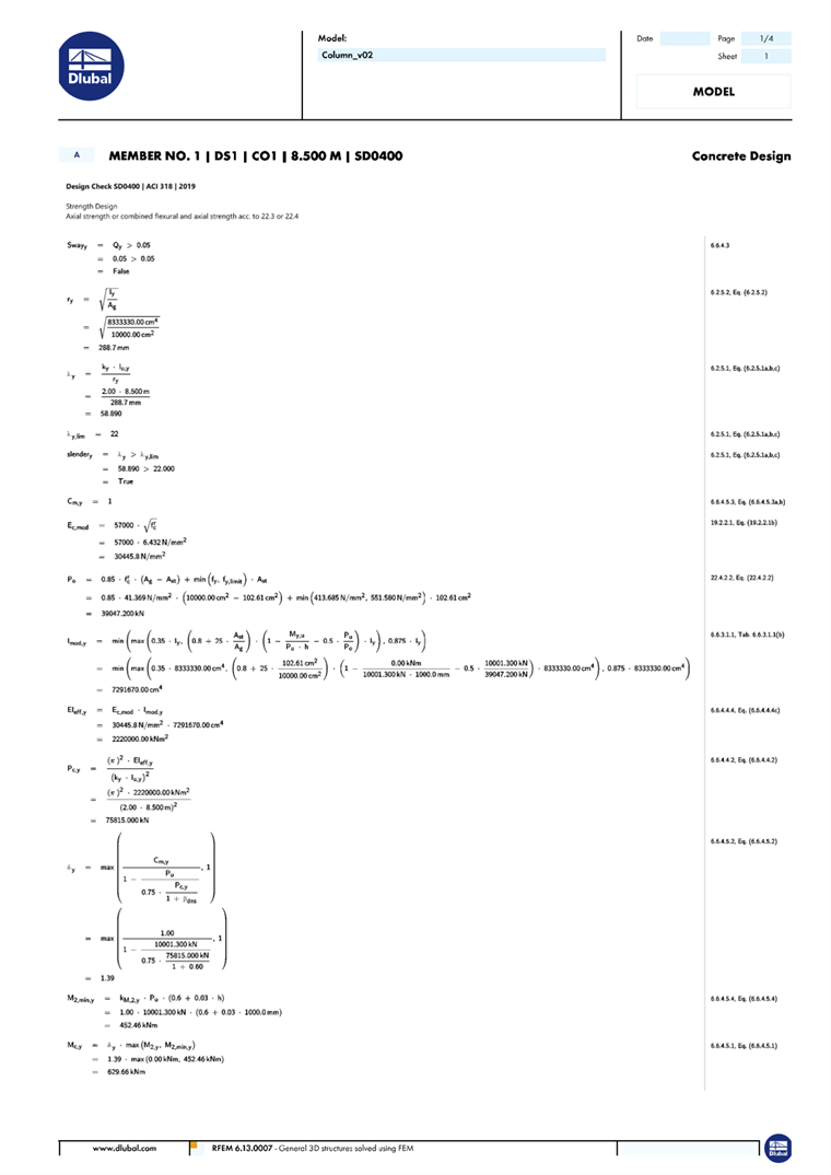
→ method c) is internally used for column design
acc. to the results:
- dns = 1.39 → smaller than ACI limit of 1.4
- the column is considered safe
- capacity ratio is 0.94
Notes
One of the key strengths of RFEM 6 is its detailed calculation report, providing essential transparency that allows engineers to confidently verify assumptions and clearly understand the governing design parameters.