


This study validates the Steel Joints add-on for RFEM by investigating the influence of bolt diameter and end-plate thickness on the capacity and failure modes of end-plated beam-to-column connections. The structural behavior and load-bearing performance of these joints are evaluated according to the design provisions of Eurocode 3 (EC-3), and the results are then compared with predictions from a finite element model developed using RFEM and the research-oriented finite element method (ROFEM).
Analytical Model
This study adopts the design criteria specified in EN 1993-1-8 for evaluating bolt resistance (shear and tension) and plate resistance (bearing and punching shear), utilizing the limit state formulations provided in Table 3.4.
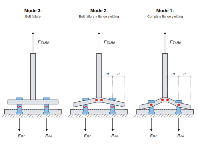
The design resistance of the equivalent T-stub is evaluated independently for the endplate and the column flange components. For each component, the governing design resistance FT,Rd is defined as the minimum value derived from three potential failure mechanisms.
The individual resistance for each mode is calculated on the basis of the plastic moment capacity of the flange (Mpl,1,Rd and Mpl,2,Rd) and the tension resistance of the bolt group (ΣFt,Rd). These modes account for complete flange yielding (Mode 1), bolt failure coupled with flange yielding (Mode 2), and pure bolt fracture (Mode 3).
Failure Modes:
Plastic Resistance Moments:
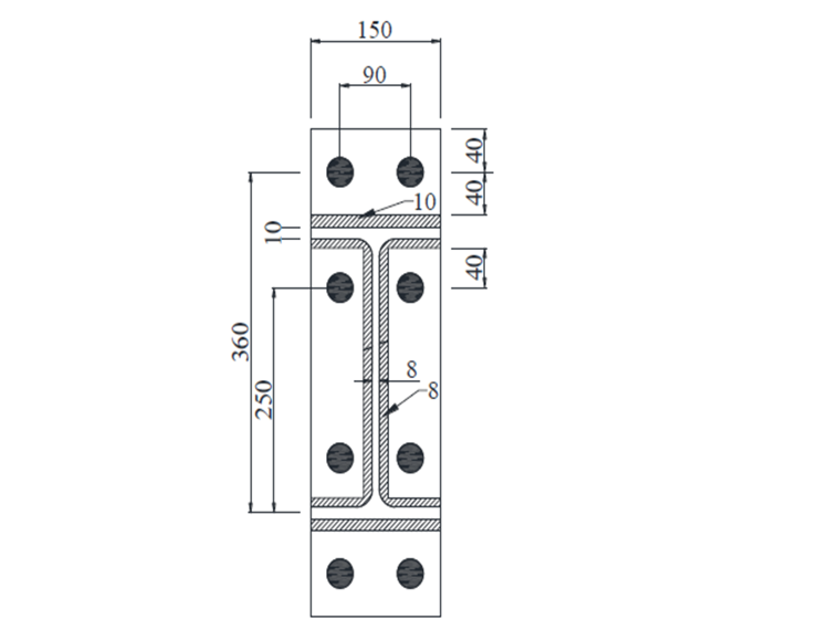
Geometric details of beam to column connection
The rigid flange was modeled as an elastic element. Material models S275 and S420 were assigned to the end plate and beam, respectively. For the parametric study, the beam was chosen to represent a typical European profile section with dimensions approximately corresponding to an IPE300 section, while the column was modeled as an HEA300 section, in accordance with the Eurocode provisions being evaluated. The dimensions of the beam and end plate are shown in Fig. 2. The variables considered in the study were bolt diameters of 16 mm (M16), 20 mm (M20), and 24 mm (M24), together with end plate thicknesses (tp) of 10 mm, 15 mm, and 20 mm.
Discussion
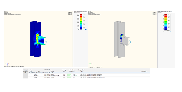
Steel Joints Add-on for RFEM Solution
This study presents a numerical investigation into the effects of bolt diameter and end plate thickness on the capacity and failure modes of extended steel end plate beam-to-column connections. The structural performance of nine such connections was examined.
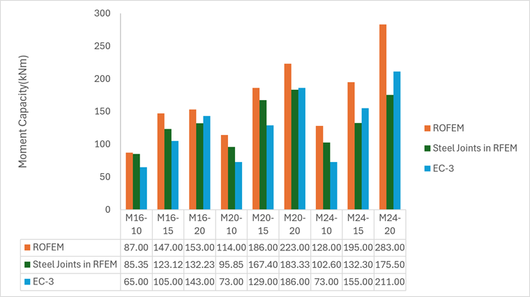
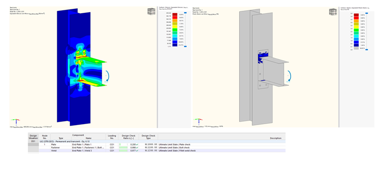
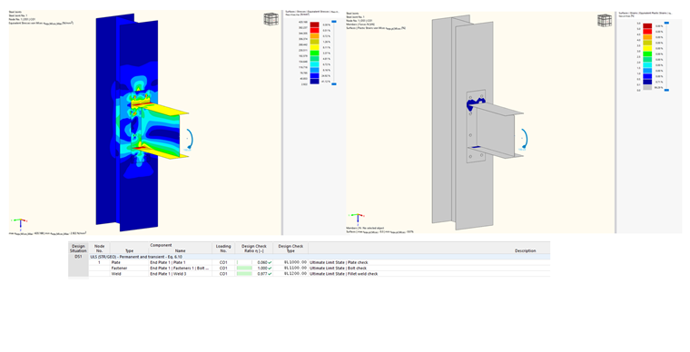
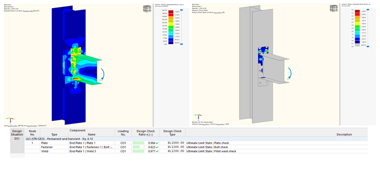
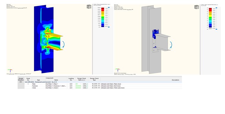
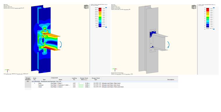
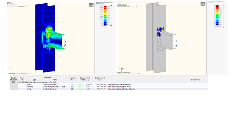
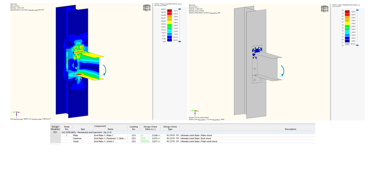
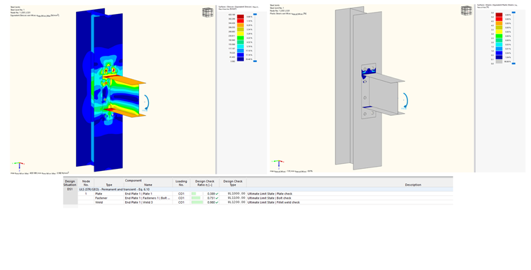
The results of the parametric study are summarized in Table 1, and the corresponding moment resistances are shown in Fig. 3. Increasing the end plate thickness produced higher plastic and ultimate moment capacities. However, once the bending moment capacity of the beam fell below that of the connection, further increases in end plate thickness had no effect on the overall capacity. The same trend was observed for bolt diameter. Table 2 shows the failure modes.
| Specimens | ROFEM | Steel Joints add-on in RFEM | EC-3 | EC-3/RFEM |
|---|---|---|---|---|
| M16-tp=10mm | 87.00 | 85.35 | 65.00 | 0.76 |
| M16-tp=15mm | 147.00 | 123.12 | 105.00 | 0.85 |
| M16-tp=20mm | 153.00 | 132.23 | 143.00 | 1.08 |
| M20-tp=10mm | 114.00 | 95.85 | 73.00 | 0.76 |
| M20-tp=15mm | 186.00 | 167.40 | 129.00 | 0.77 |
| M20-tp=20mm | 223.00 | 183.33 | 186.00 | 1.01 |
| M24-tp=10mm | 128.00 | 102.60 | 73.00 | 0.71 |
| M24-tp=15mm | 195.00 | 132.30 | 155.00 | 1.17 |
| M24-tp=20mm | 283.00 | 175.50 | 211.00 | 1.20 |
| Specimens | ROFEM | Steel Joints add-on in RFEM | EC-3 |
|---|---|---|---|
| M16-tp=10mm | Mode 1 | Mode 1 | Mode 1 |
| M16-tp=15mm | Mode 1 | Mode 1 | Mode 1&2 |
| M16-tp=20mm | Mode 2 | Mode 2 | Mode 2&3 |
| M20-tp=10mm | Mode 1 | Mode 1 | Mode 1 |
| M20-tp=15mm | Mode 1 | Mode 1 | Mode 1&2 |
| M20-tp=20mm | Mode 2 | Mode 2 | Mode 1&2 |
| M24-tp=10mm | Mode 1 | Mode 1 | Mode 1 |
| M24-tp=15mm | Mode 1 | Mode 1 | Mode 1 |
| M24-tp=20mm | Mode 1 | Mode 1 | Mode 1&2 |
Conclusions
Three methods—a detailed FE model (ROFEM), the component-based Steel Joints add-on in RFEM, and the EC-3 (EN 1993-1-8) component method—were compared across nine bolted end plate connections (M16/M20/M24 bolts × 10/15/20 mm plates).
The EC-3/RFEM ratio is governed by plate thickness, rising monotonically within each bolt group: EC-3 substantially underestimates the resistance for 10 mm plates (0.71-0.76) but overtakes the RFEM for 20 mm plates (1.01-1.20). The reason is mechanical—thin plates fail by ductile plate yielding (Mode 1), whereas the FE methods capture the membrane action and strain hardening that the EC-3 T-stub model omits.
As the plate thickens and the bolt becomes the weak component, that margin disappears. On failure modes, ROFEM and RFEM agree in every specimen; EC-3 agrees on the governing component but tends to flag combined modes (1&2, 2&3). The pattern follows the classic T-stub theory: thicker plates shift failure toward bolt control, while larger bolts keep the joint in ductile Mode 1.
The initial stiffness of an end plate connection rises with increasing bolt diameter or end plate thickness. The Eurocode predicts the failure modes of such connections with a high degree of accuracy.