


Adding a Member Transverse Weld
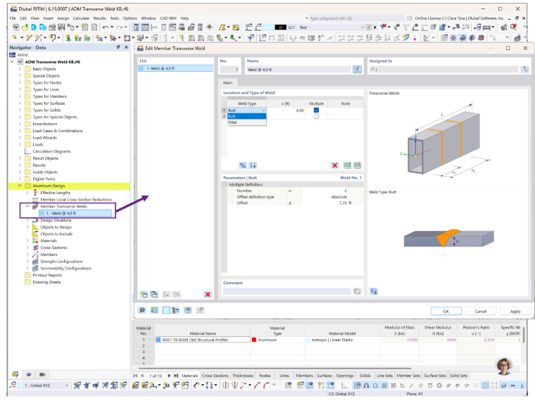
The Member Transverse Welds option is located in the Aluminum Design folder. Specify the weld type and weld location along the member. Multiple weld locations, such as welds at both member ends, can be defined by enabling the Multiple option (Image 1).
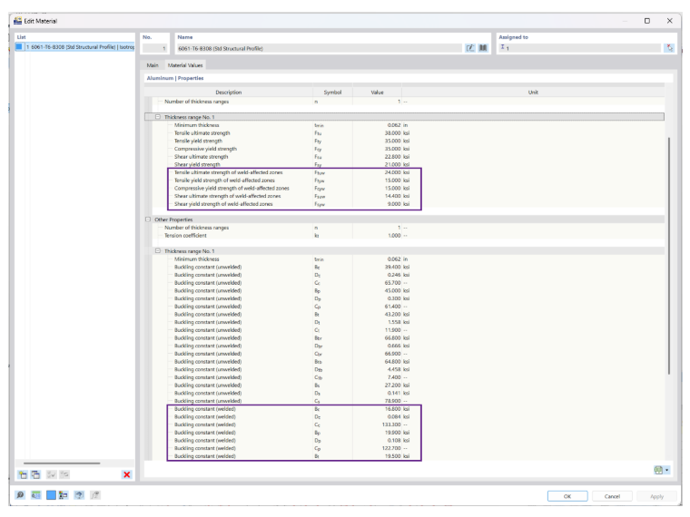
The weld-affected zone strengths and the applicable welded buckling constants listed under Material Values are used in the design calculations (Image 2). For members with transverse welds located more than 0.05 times the member length from either end, the member buckling strength is determined as though the entire member were weld-affected, in accordance with ADM Section E.2.
Example
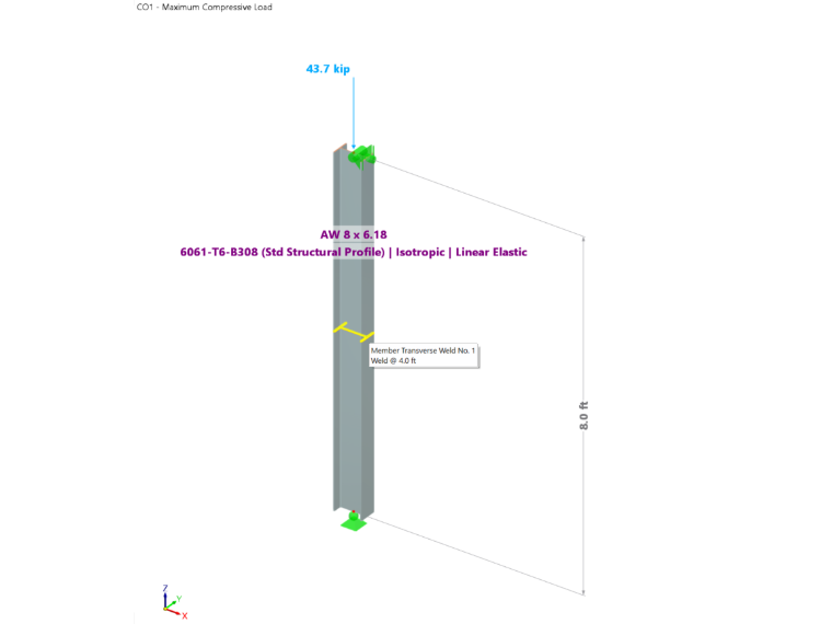
Example 11 from the Aluminum Design Manual (ADM) 2020 is used to verify the RFEM results. An 8-ft-long AW 8 × 6.18 W-shape column with pinned ends is subjected to a compressive load of 43.7 kips and contains a transverse weld at its midpoint (Image 3). The column is laterally braced against weak-axis buckling, and both ends are restrained against torsion. An effective length factor of kx = 0.5 for torsional buckling is specified in the effective length input.
Results
The available compressive strength is evaluated based on the following limit states:
- ADM Section E.2 – Member buckling
- ADM Section E.3 – Local buckling (Weighted Average Method or Direct Strength Method)
- ADM Section E.4 – Interaction between member buckling and local buckling
After running the Aluminum Design calculation using the ASD design method, the results are displayed in the Design Ratios by Member table. Select design check EE2000 to review the local buckling calculation (Image 4).
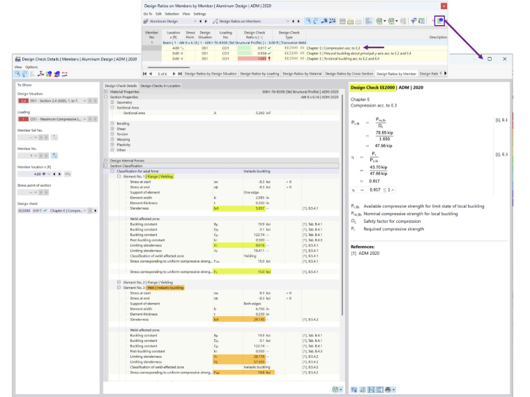
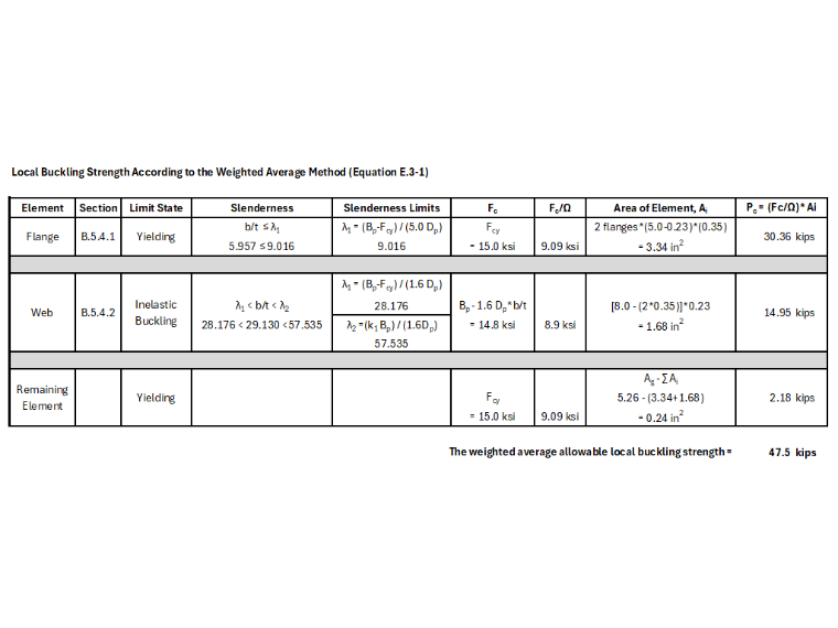
For members containing transverse welds, the local buckling strength is determined using the Weighted Average Method of ADM Section E.3 [1]. The design check details do not include the intermediate calculations; therefore, these calculations are presented separately in Image 5.
Summary
The Aluminum Design add-on provides a straightforward method for accounting for the reduced strength of weld-affected zones in aluminum members. Comparison with the ADM design example demonstrates that the add-on produces accurate results for transverse weld design. Any minor differences are attributable to rounding.
 Knowledge Base