57 Results
View Results:
Sort by:

Creating a validation example for Computational Fluid Dynamics (CFD) is a critical step in ensuring the accuracy and reliability of simulation results. This process involves comparing the outcomes of CFD simulations with experimental or analytical data from real-world scenarios. The objective is to establish that the CFD model can faithfully replicate the physical phenomena it is intended to simulate. This guide outlines the essential steps in developing a validation example for CFD simulation, from selecting a suitable physical scenario to analyzing and comparing the results. By meticulously following these steps, engineers and researchers can enhance the credibility of their CFD models, paving the way for their effective application in diverse fields such as aerodynamics, aerospace, and environmental studies.

When wind-induced surface pressures on a building are available, they can be applied on a structural model in RFEM 6, processed by RWIND 2, and used as wind loads for static analysis in RFEM 6.
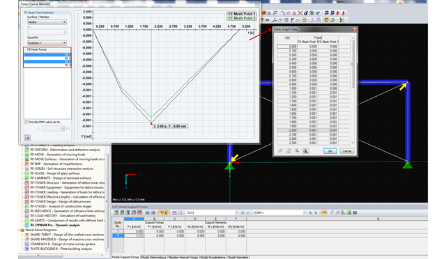
RF-/DYNAM Pro - Forced Vibrations provides the option of a time course monitor. During the evaluation process, you can compare several graphs directly in the program. In addition, you can transfer the figures to the printout report or export them directly to Excel as a value table.
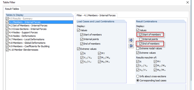
A successful project process involves not only the building owner and the engineer, but also the designers. These days, they also have to design standard connections in steel structures themselves. To do this, the corresponding internal forces of connections are required.

The automatic surface reinforcement design process determines a surface reinforcement that covers the required amount of reinforcement.
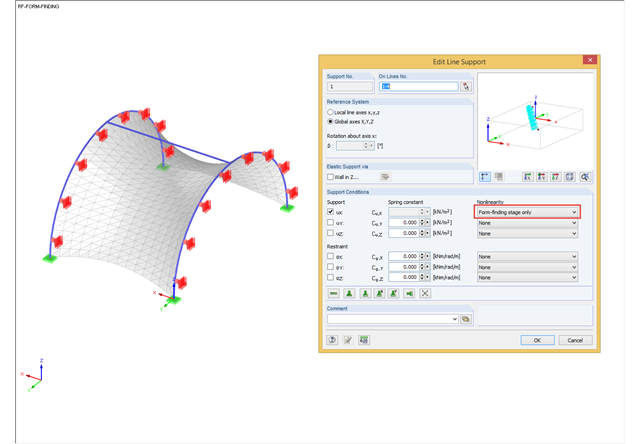
During the form-finding process, the slip modulus of a substructure is also taken into account when searching for the equilibrium state. You can also consider large deflections of supporting trusses or pure bending deformation of the edge beams when determining the membrane shape.
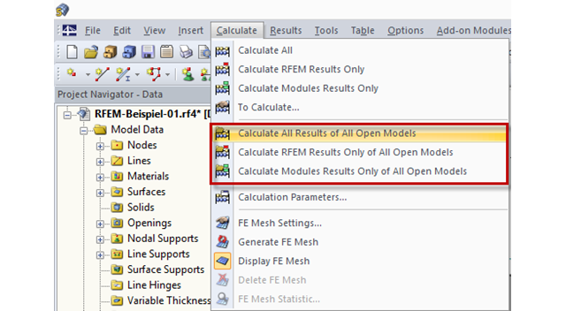
In RFEM and RSTAB, files can be computed automatically in a sequence of calculation, so the models can be processed overnight, for example.

The classification of cross-sections according to EN 1993‑1‑1 and EN 1993‑1‑5 can be carried out automatically in the RF‑/STEEL EC3 add-on module. The maximum c/t ratios are specified in the standard for straight cross-section parts. There are no normative specifications for curved cross-section parts; therefore, the cross-section classification cannot be performed for these cross-section parts.

The form-finding process in RF-FORM-FINDING displaces the corner nodes of FE elements of a membrane surface in space until the defined surface stress is in equilibrium with the boundary conditions. This displacement is independent of the element geometry. In the case of elements with four corner nodes, the free displacement may cause spatial drilling in the element plane and thus exceed the validity limits of the calculation; therefore, triangular elements are generally recommended for form‑finding systems. Triangular elements remain independent of the corner node displacement and stay within the calculation limitations.
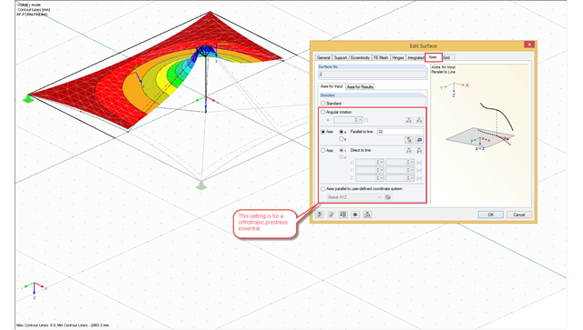
The form-finding process in RFEM seeks an equilibrium state where the defined prestress of membranes and the prestress or length changes of cable elements with boundary reactions are in equilibrium. For this, the program provides the option to define an isotropic or an orthotropic prestress state for membranes.