10 Results
View Results:
Sort by:
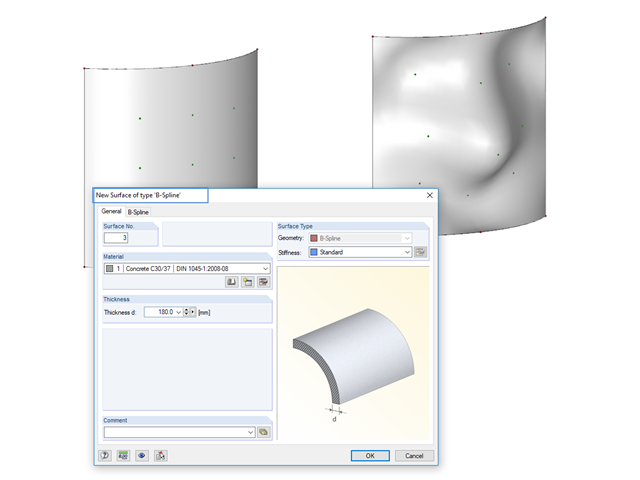
Instead of a quadrangular surface, you can use a B‑spline surface. The shape of this can be adjusted retrospectively, using the integrated help nodes. Depending on the necessary surface complexity, you can create a B‑spline surface with 3 × 3 or 4 × 4 help nodes.

In order to detect the governing internal forces of a plate, a checkerboard loading is commonly used. Since it is not necessary to divide the surface into individual load segments, loading is usually carried out by means of free rectangular loads. In the case of many loads, the normal load display can become somewhat confusing.
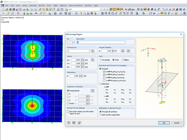
RFEM 5 provides the option to define a smoothing area in the "Results" → "New Average Region" menu. You can choose a rectangular, circular, or elliptical shape. With this tool you can, for example, "smooth" singularities due to nodal loads in a desired averaged region.

The wind load of rectangular rounded structural components is a complex matter. The equivalent forces from wind load depend on the strength of the circulating wind load and the component geometry.
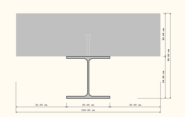
There are different options to model composite cross‑sections in RFEM. In the following example, three different modeling options for a composite cross‑section, consisting of a rolled steel section HEA 300 and a rectangular cross‑section made of concrete w/l = 100/30 cm will be displayed and explained.
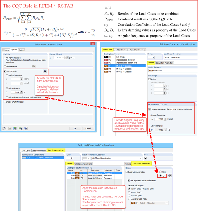
The CQC (Complete Quadratic Combination) rule has been available in RFEM and RSTAB since version X.06.3039. In the General Data of the model you can activate the CQC rule, and for Load Cases of the "Earthquake" type two new properties are available: "Angular frequency" and "Lehr's damping".

The form-finding process in RF-FORM-FINDING displaces the corner nodes of FE elements of a membrane surface in space until the defined surface stress is in equilibrium with the boundary conditions. This displacement is independent of the element geometry. In the case of elements with four corner nodes, the free displacement may cause spatial drilling in the element plane and thus exceed the validity limits of the calculation; therefore, triangular elements are generally recommended for form‑finding systems. Triangular elements remain independent of the corner node displacement and stay within the calculation limitations.
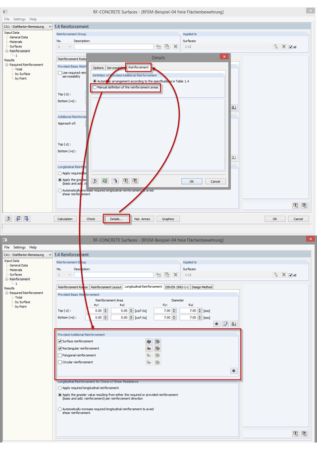
As of program version RFEM 5.06, you can not only perform the automatic arrangement of an additional reinforcement, but also define the surface reinforcement manually. In addition to the uniformly distributed basic reinforcement, you can define various surface reinforcements (per surface; rectangular, circular, or polygonal).
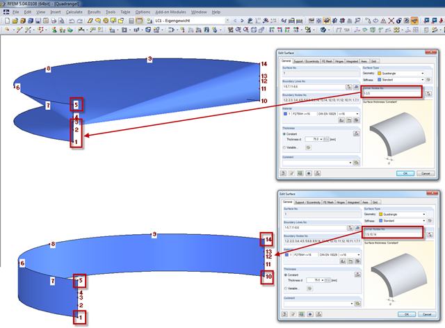
When creating a quadrangular surface, RFEM can automatically detect the four corner nodes. For more complex structures, it can happen that the optimal corner nodes are not found. Manually entering the four corner nodes can lead to a better result, in this case.
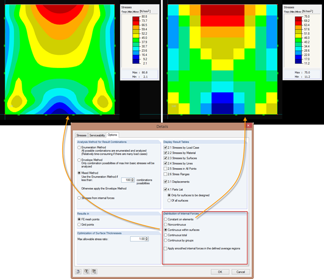
Just as in the RFEM Display Navigator, you can set the distribution of internal forces in surfaces in RF‑STEEL Surfaces. Since deformations are always the result of the FEM calculation, the corresponding forces will be recalculated. This means that the internal forces on an FEM element are calculated depending on the composition (triangular or square) in three or four places. In order to obtain continuous internal forces and thus a smoothed distribution, these internal forces have to be interpolated. Interpolation is done by selecting the "Distribution of internal forces" option in the surfaces.