9 Results
View Results:
Sort by:
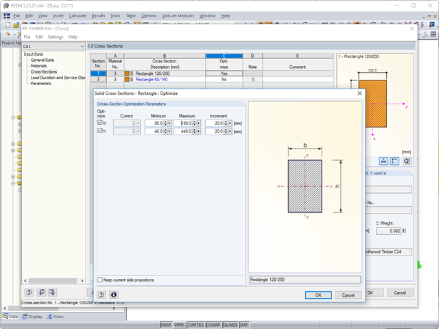
In the course of a reasonable pre-dimensioning of cross-sections, you can optimize the cross-sections of the corresponding section series in the RF‑/TIMBER Pro add-on module.

When optimizing cross-sections in the add-on modules, you can also select arbitrarily defined cross-section favorites lists - in addition to the cross-sections from the same cross-section series as the original cross-section.
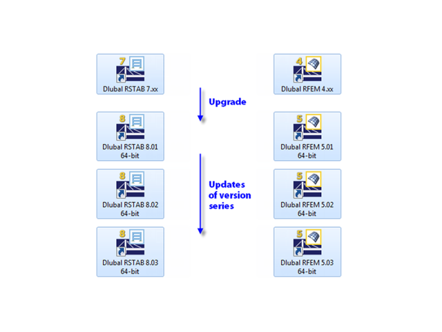
When updating within a version series (for example, RFEM 5.01.01 to 5.01.02), the old program files are removed and replaced by new ones. The project data, of course, remain unchanged. When updating to the next version series (for example, RFEM 5.02.01), the new version is installed in parallel. The program files are located in different directories, so the previous version is still available.
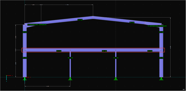
Part 4.1 of this article series describes the connection of the RF‑/STEEL EC3 add‑on module; the members and load combinations to be designed were already defined. This section will focus on the optimization of cross‑sections in the module and the transfer to RFEM. The elements already explained in the previous parts are not described again.
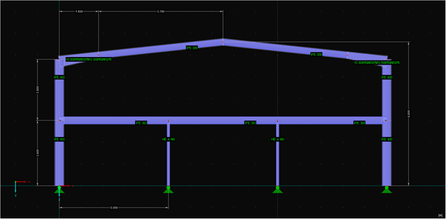
Sections 4.1 and 4.2 of this article series describe the optimization of a frame using the RF‑/STEEL EC3 add-on module. The fifth section explains how to link the module and get the relevant members. The elements already explained in the previous sections will not be described again.
Part 2.2 of the article series about the COM interface describes creating and modifying nodal supports, loads, load cases, load combinations, and result combinations on an example of a member. The fourth part explains creating individual tools.

The following article describes a design using the equivalent member method according to [1] Section 6.3.2, performed on an example of a cross-laminated timber wall susceptible to buckling described in Part 1 of this article series. The buckling analysis will be performed as a compressive stress analysis with reduced compressive strength. For this, the instability factor kc is determined, which depends primarily on the component slenderness and the support type.
Part 2.1 of the article series about the COM interface described creating and modifying elements on an example of a member. In the third part, these core elements are used again to create nodal supports, loads, load combinations, and result combinations. Thus, the model created in the second part will be extended. Therefore, the elements explained in Part 1 and Part 2.1 are not described again.
The first part of the article series about the COM interface described opening and creating a model in RFEM. The second part explains creating and modifying elements on an example of a member. The elements described in Part 1 will not be explained again here.