6 Results
View Results:
Sort by:
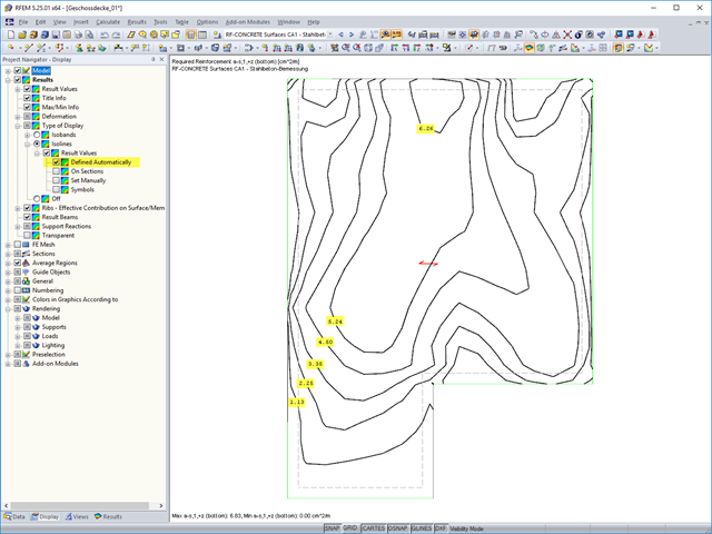
The results of an FEM calculation are usually documented by means of isobands and isolines in the graphical display of results. In the following, we will look at creating the results graphic for the black-and-white printout.
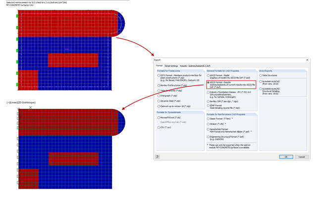
Until program version RFEM 5.06.1103, it was only possible to export the results on surfaces in the form of isolines into a DXF file. With program version 5.06.3039, you can now also export the results in the Isobands display option.
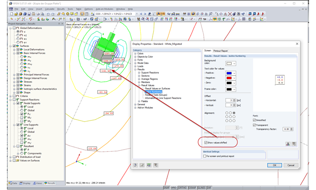
In the case of very small distances between isolines, the labels often overlap, which makes the result documentation difficult. As of RFEM version 5.06, you can select a shifted arrangement of the isoline labels in the Display Properties dialog box. By selecting the "Show values shifted" option, you can easily avoid overlapping the result values in many cases.
RF‑CONCRETE Surfaces performs the ultimate and the serviceability limit state design of slabs, plates, folded plates, and shells. In RFEM 5, the reinforcement resulting from this design can be displayed graphically on the surfaces of the structure using isolines. For the reinforcement design, it may be useful to export the results as isoline distribution in a DXF file in order to open them in a CAD application as background layers.
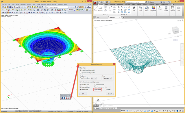
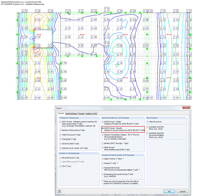
In RFEM, there are a file‑based and a direct DXF interface. The file-based DXF interface allows you to export the data in a DXF file that is transferred directly into an open AutoCAD file. In the interface dialog box, you can select which data are to be exported (results as isolines, result values, or finite element mesh with boundary and integration lines).
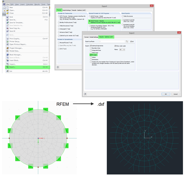
In RFEM, you can use the export function to export the generated FE mesh in DXF as a result. To do this, open the export dialog box in the program and select "ASCII Format - Results". In addition to a result (for example, isolines), you can select the FE Mesh in the "Results - Isolines (.dxf)" tab. After the export, the mesh in DXF is available in the DL‑FE‑MESH layer.