11 Results
View results:
Sort by:

Imperfections in construction engineering are associated with production-related deviation of structural components from their ideal shape. They are often used in a calculation to determine the equilibrium of forces for structural components on a deformed system.

With the RF-/TIMBER Pro add-on module, you can perform the vibration design known from DIN 1052 for the design according to EN 1995-1-1. In this design, the deflection under permanent and quasi-permanent action at the ideal one‑span beam may not exceed the limit value (6 mm according to DIN 1052). If you consider the relation between the natural frequency and the deflection for a hinged single-span beam subjected to a constant distributed load, the 6 mm limit value results in a minimum natural frequency of about 7.2 Hz.
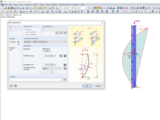
In the world of construction engineering, the word "imperfections" has a specific meaning. In general, it describes the incompleteness of a structure or the deviation of a structural component from an ideal shape caused by the production.
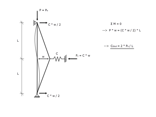
If a member is supported laterally to prevent buckling due to a compressive axial force, it must be ensured that the lateral support is actually able to prevent buckling. Therefore, the aim of this article is to determine the ideal spring stiffness of a lateral support using the Winter model.

Closed circular cross-sections are ideal for welded truss structures. The architecture of such constructions is popular when designing transparent roofs. This article shows the special features of the connection design using hollow sections.

When designing steel columns or steel beams, it is usually necessary to carry out cross-section design and stability analysis. While the cross-section design can usually be performed without giving further details, the stability analysis requires further user-defined entries. To a certain extent, the member is cut out of the structure; therefore, the support conditions have to be specified. This is particularly important when determining the ideal elastic critical moment Mcr. Furthermore, it is necessary to define the correct effective lengths Lcr. These are required for the internal calculation of slenderness ratios.

This example is described in technical literature [1] as Example 9.5 and in [2] as Example 8.5. A lateral-torsional buckling analysis must be performed for a principal beam. This beam is a uniform structural member. Therefore, the stability analysis can be carried out according to Clause 6.3.3 of DIN EN 1993‑1‑1. Due to the uniaxial bending, it would also be possible to perform the design using the General Method according to Clause 6.3.4. Additionally, the determination of the critical load factor is validated with an idealized member model in line with the method mentioned above, using an FEM model.

This example is described in technical literature [1] as Example 9.5 and in [2] as Example 8.5. A lateral-torsional buckling analysis must be performed for a principal beam. This beam is a uniform structural member. Therefore, the stability analysis can be carried out according to Clause 6.3.3 of DIN EN 1993-1-1. Due to the uniaxial bending, it would also be possible to perform the design using the General Method according to Clause 6.3.4. Additionally, the determination of the moment Mcr is validated with an idealized member model in line with the method mentioned above, using an FEM model.
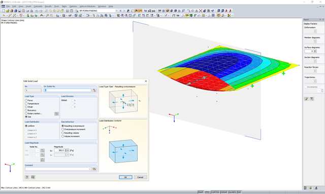
In theory, an ideal gas consists of freely moving mass particles without extension in a volume space. In this space, each particle moves at a speed in one direction. The collision of one particle with another particle or the volume limitations leads to a deflection and a change in the speed of the particles.
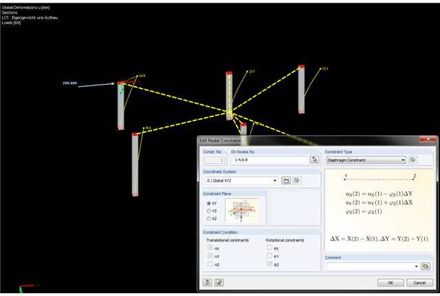
In the latest version of RFEM, nodal constraints were implemented. Therefore, you can now connect the nodes in an ideal way. The diaphragm type represents the option to couple nodes in a plane. This option is available not only for the global coordinate system, but also for user-defined coordinate systems.

In RFEM, you have the option to create and analyze cables using sheaves. For this, use the "Cable on Pulleys" member type. It is ideal for pulley systems, where the longitudinal forces are transferred via sheaves.