Imperfections are often used in a calculation when you need to determine the equilibrium of forces for structural components on a deformed system. It is this nonlinear calculation in connection with the mentioned deformation of the structural component that results in an increase of internal forces and deformations as compared to a linear calculation. Nonetheless, these increased internal forces and deformations can be used in most cases to obtain a considerably more efficient design of the structural component, compared to a simple design in which the imperfection of the structural component is taken into account by increase factors.
Design standards, such as EN 1993‑1‑1, allow for the simulation of imperfections by means of equivalent loads. The magnitude of the equivalent load is defined by the acting axial force of the structural component and its buckling behavior.
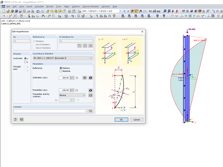
In order to represent any form of imperfection as much as possible, there is an inclination imperfection and a precamber imperfection. The inclination imperfection simulates a component as inclined over its entire length. The precamber imperfection simulates a straight structural element as a bow.
Our programs can simulate these kinds of imperfections by member imperfections. Member imperfections are organized as a load in the program. This attribute helps to add up the member imperfections as a load case to other load case series. Thus, you have the possibility to check different imperfection geometries by different load case series in a computational model.
Example:
LC1 = Self-weight
LC2 = Imposed load
LC3 = Imperfection in the X‑direction
LC4 = Imperfection in the Y-direction
CO1 = 1.35 ⋅ LC1 + 1.5 ⋅ LC2 + 1.0 ⋅ LC3 ... Load combination with imperfection in X
CO2 = 1.35 ⋅ LC1 + 1.5 ⋅ LC2 + 1.0 ⋅ LC4 ... Load combination with imperfection in Y
The program then determines the axial force for each load combination separately and includes it in the equivalent load calculation. Since this axial force can change in the respective iterations because of the geometrically nonlinear calculation, the axial force for the equivalent load of the imperfection is checked and, if necessary, modified after each iteration. For structural components with a variable axial force distribution, the axial force average for the imperfection load is used over the member length.