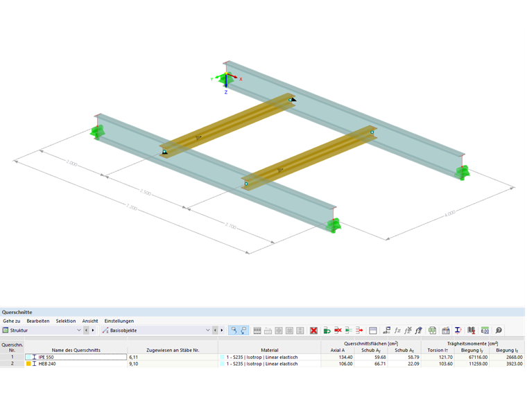
Structural System
Cross-Sections:
Principal beams = IPE 550
Secondary beams = HE-B 240
Material:
Structural steel S235 according to DIN EN 1993-1-1, Table 3.1
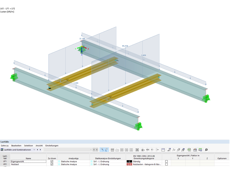
Design Loads
LC 1 Self-weight:
gd = 1.42 kN/m
LC 2 Imposed load:
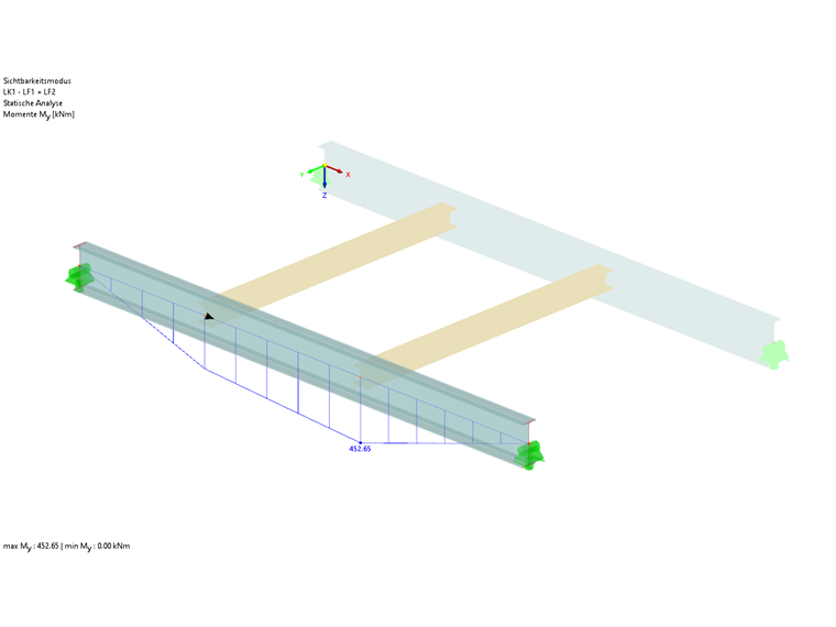
Design Internal Forces
Stability Analysis Without Considering Secondary Beams According to EN 1993-1-1, Section 6.3.2
Under the assumption of a lateral and torsional restraint available at the member's start and end, an ideal critical moment for lateral torsional buckling Mcr of 365 kNm is determined in the "Steel Design" add-on in line with the verification according to [3], Section 6.3.2. Thus, the design according to Equation 6.55 results in 1.65. Hence, the ultimate limit state design cannot be fulfilled without the stabilizing effect of the secondary beams.
Stability Analysis Considering Secondary Beams According to EN 1993-1-1, Annex BB.2.2
The rules of DIN EN 1993-1-1, Annex BB.2.2 assume a continuous rotational restraint over the beam's length. Therefore, the discrete rotational restraint available in the model is "smeared" to a continuous rotational restraint.
Determination of available continuous rotational restraint:
The values are taken from [2] and only adjusted to the notation of Annex BB.2.2.
Cθ,R,k = 11,823 kNm (a component due to the flexural deformation of the secondary beams)
Cθ,D,k = 359 kNm (a component due to the cross-section deformation of the principal beam, the connection to the web is considered)
Conversion to continuous rotational restraint Cθ based on the secondary beams with the average distance of the secondary beams:
Determination of the required rotational restraint:
where:
Kυ = 0.35 for the elastic cross-section ratio
Kθ = 10 according to DIN EN 1993-1-1/NA, Table BB.1
A reduction of Cθ,min by (MEd / Mel,Rd)² is possible:
Design:
Cθ,prov = 134 kNm/m < Cθ,min = 200.9 kNm/m
The design in the form of the verification of a sufficient restraint for the principal beam's lateral deformation according to Annex BB.2.2 cannot be performed.
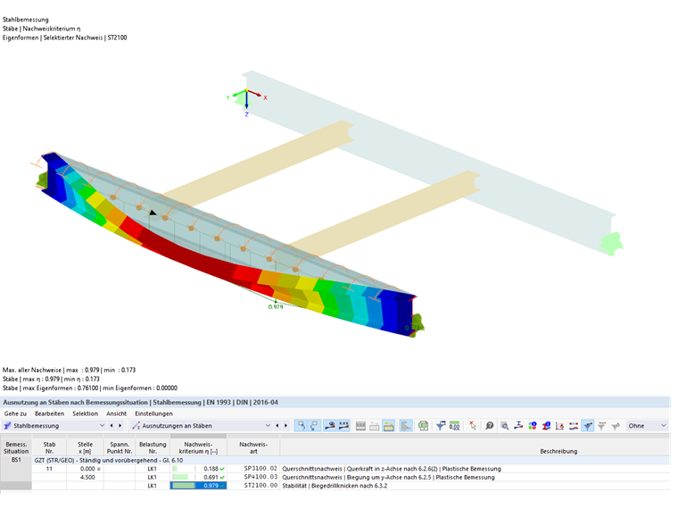
Stability Analysis Considering Secondary Beams According to EN 1993-1-1, Section 6.3.2, with Continuous Rotational Restraint
Since the design of a sufficient lateral restraint according to Annex BB.2.2 could not be performed, the existing rotational restraint is further integrated into the design of the structural system according to Section 6.3.2 to check whether it is sufficient.
Due to the applied continuous rotational spring stiffness of Cθ, prov = 134 kNm/m, the idealized lateral-torsional buckling moment is increased to Mcr = 982 kNm. It results from the multiplication with the design bending moment and the amplifier αcr, with which the minimum elastic critical buckling load with deformations from the structural system plane is reached. The factor acr is 2.169 due to the continuous rotational restraint. Thus, the application of a rotational restraint has a favorable effect on the design, so the design according to Equation 6.55 is finally 0.979.
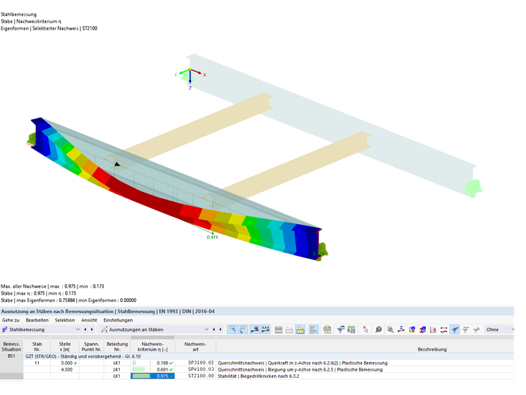
Stability Analysis Considering Secondary Beams According to EN 1993-1-1, Section 6.3.4, with Discrete Rotational Restraint
In the following, the application of a discrete rotational restraint will be analyzed.
Determination of the available discrete rotational restraint:
The values are taken from [2] and only adjusted to the notation of Annex BB.2.2.
Cθ,R,k = 11,823 kNm (a component due to the flexural deformation of the secondary beams)
Cθ,D,k = 359 kNm (a component due to the cross-section deformation of the principal beam, the connection to the web is considered)
For the design according to 6.3.2, an amplifier of αcr = 2.196 is determined with the discrete rotational restraint. The result is a moment Mcr of 452.65 kNm ∙ 2.196 = 994.09 kNm.
The design according to Equation 6.55 thus results in 0.975 for the structural system.
Stability Analysis Considering Secondary Beams According to Second-Order Analysis with 7 DOF (Warping Torsion)
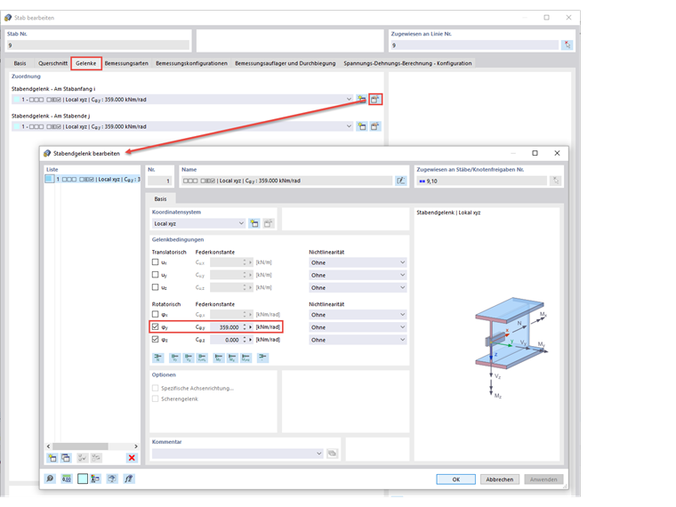
For this design, it is necessary to activate the "Structure Stability" and "Torsional Warping" add-ons in the Base Data. Furthermore, it is important to deactivate the stability analysis in the design configurations, since the design checks should be performed in the form of cross-section design checks according to the second-order analysis, taking into account the imperfection and applying γm1. Subsequently, the member hinges of the secondary beams are modified.
When determining the existing discrete rotational restraint, the component from the bending deformation of the secondary beams Cθ,R,k is omitted, because the interaction of the principal and secondary beams is already included in the model with 7 degrees of freedom. Thus, it is only necessary to consider the spring from the cross-section deformation of the principal beam with Cθ,D,k = 359 kNm. This spring constant is used to modify the member hinges of the secondary beams. In addition, it must be ensured that all acting loads are applied at the upper edge of the section or in an unfavorable, eccentric position.
Since the calculation is performed according to the second-order analysis, it is also necessary to consider the imperfections. This is done by determining the buckling or lateral-torsional buckling shape using the "Structural Stability" add-on. For this, the applied load combination (here: CO1) calculates the critical load according to the linear static analysis and then generates the imperfection on the basis of the resulting mode shape.
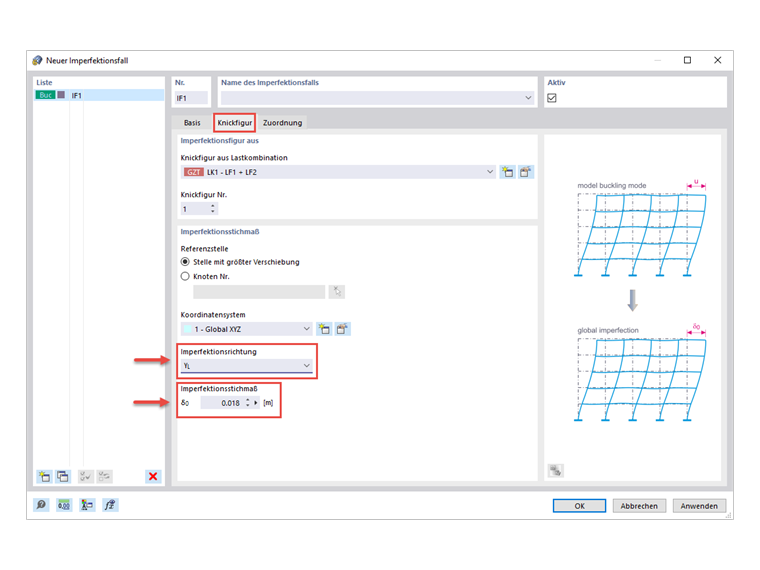
In order to create this imperfection, it is necessary first to create a new imperfection case, which is based on the buckling shape due to the load combination. Among other things, an imperfection magnitude has to be specified, which results from the multiplication of the cross-section design ratio e0/L and the length L of the cross-section. The cross-section ratio depends on the cross-section type and dimensions. Since the principal beams of the model consist of rolled I-sections with the dimensions h/b > 2, the cross-section ratio e0/L = 1/400 applies. With the cross-section length of L = 7.20 m, the resulting imperfection dimension is finally 0.018 m in the y-direction.
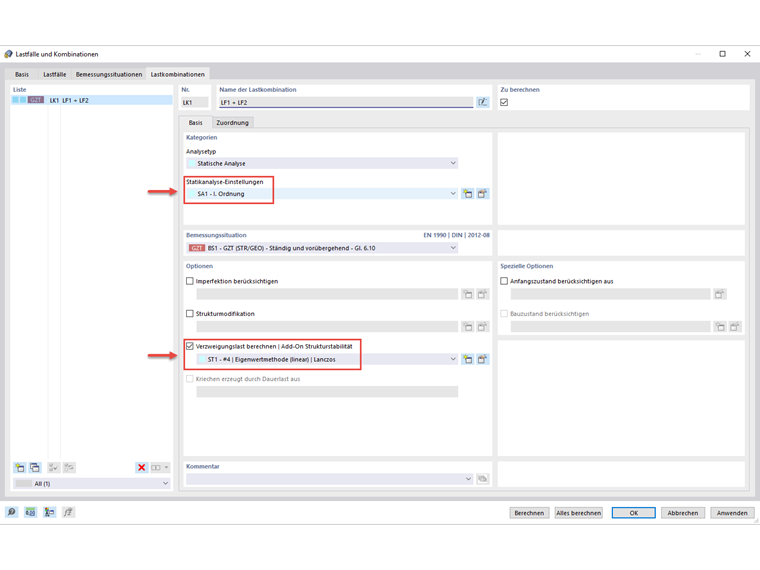
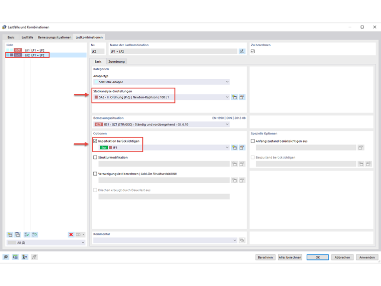
Now, it is necessary to assign this imperfection case to the load combination. To avoid a circular reference, a new load combination is created by copying the CO which the imperfection is based on and calculating it according to the second-order analysis.
When performing the steel structure design, the cross-section design is now carried out according to the second-order analysis, taking into account the imperfection. Based on the determined internal forces, the design ratio of 0.987 is finally obtained according to Eq. 6.1.
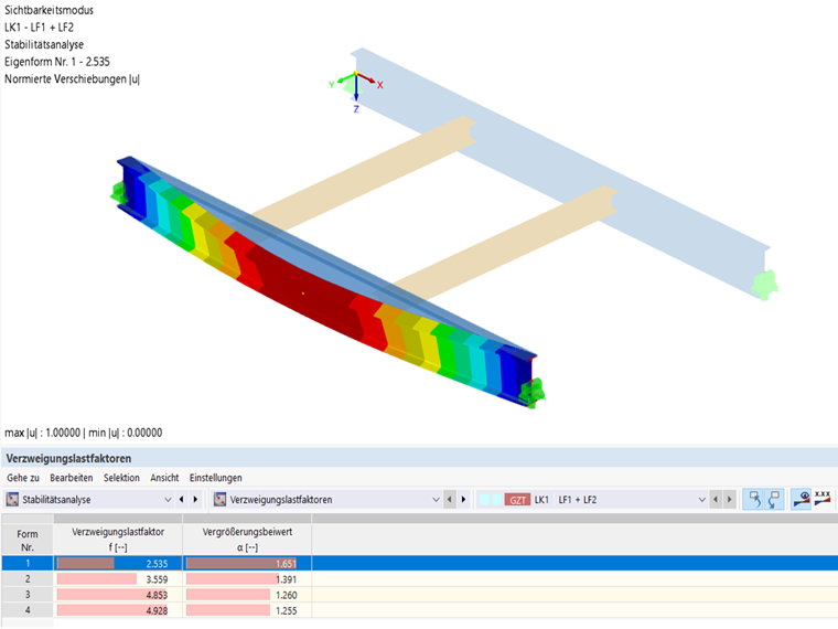
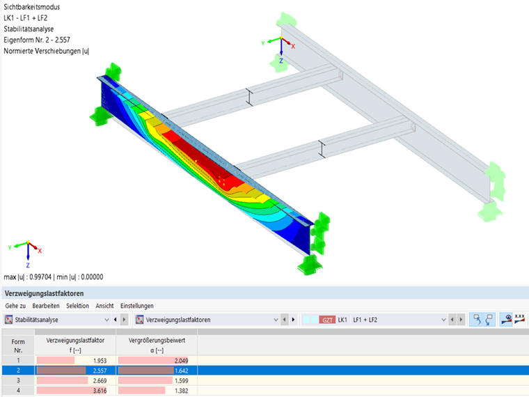
Verification of Design Correctness Using FEA Model
During the stability analysis of CO1 on the model with 7 degrees of freedom, a critical load factor of 2.535 was used, which should be subsequently validated using an FEA model.
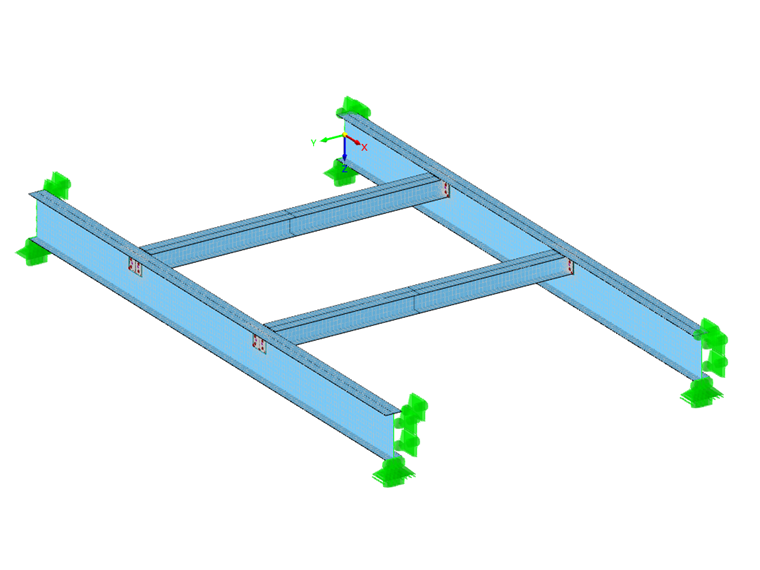
The FEA model is used to check whether the system with 7 degrees of freedom in combination with the stability was calculated correctly. The FEA model represents the system as before, so the connections of the secondary beams were also modeled as hinged with end plates and the loads were applied to the top flange of the beams. A stability analysis is now carried out on this structural system. As a result, we also obtain the torsional buckling of the top flange with a critical load factor of 2.557; that is, almost the same as the one of the system with 7 degrees of freedom.