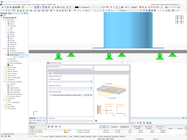
Make your work easier. A surface contact serves to describe a contact definition between two or more surfaces that are at a distance from each other It is no longer necessary to create a contact solid between the surfaces.
Go to Explanatory Video
The nonlinear calculation adopts the real mesh geometry of planar, buckled, simple curved, or double curved surface components from the selected cutting pattern and flattens this surface component in compliance with the minimization of distortion energy, assuming defined material behavior.
In simplified terms, this method attempts to compress the mesh geometry in a press, assuming frictionless contact, and to find the state in which the stresses from flattening in the component are in equilibrium in the plane. This way, minimum energy and optimum accuracy of the cutting pattern are achieved. Compensation for warp and weft as well as compensation for boundary lines are considered. Then, the defined allowances on boundary lines are applied to the resulting planar surface geometry.
Features:
- Minimization of distortion energy in the flattening process for very accurate cutting patterns
- Application for almost all mesh arrangements
- Recognition of adjacent cutting pattern definitions to keep the same length
- Mesh application for main calculation

- Design of knee joints, T-joints, cross joints, and continuous column connections with I-shaped sections
- Import of geometry and load data from RFEM/RSTAB or manual specification of the connection (for example, for recalculation without an existing RFEM/RSTAB model)
- Flush top connections or connections with bolt row in extension
- Design of positive and negative frame joint moments
- Various inclinations of right and left horizontal beams as well as application to frames of duopitch and monopitch roofs
- Consideration of additional flanges in a horizontal beam, for example for tapered sections
- Symmetrical and asymmetrical T-joints or cross joints
- Two-sided connection with different cross-section depth on the right and left
- Automatic preliminary design of bolt layout and required stiffening
- Optional design mode with possibility to specify all bolt spacing, welds, and sheet thicknesses
- Screwability check with adjustable dimensions of used wrenches
- Connection classification by stiffness and calculation of the spring stiffness of connections considered in the internal forces determination
- Check up to 45 individual designs (components) of the connection
- Automatic determination of governing internal forces for each individual design
- Controllable connection graphics in rendering mode with specifications of material, sheet thickness, welds, bolt spacing, and all dimensions for construction
- Integrated and flexibly extensible settings of National Annexes according to EN 1993-1-8 standard
- Automatic conversion of internal forces from structural analysis into respective sections, also for eccentric member connections
- Automatic determination of initial stiffness Sj,ini of the connection
- Detailed plausibility check of all dimensions, including specifications of input limits (for example, for edge distances and hole spacing)
- Optional application of compression forces to a column through contact
- Possibility to update the cross-section depth of horizontal beams in case of tapered connections after connection geometry optimization in RF-/FRAME-JOINT Pro
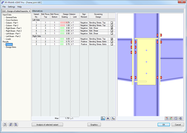
The RF-/FRAME-JOINT Pro add-on module performs the following designs according to the standards EN 1993-1-8 or DIN 18800:
- Beam end plate and column flange according to the plastic hinge theory
- Tension of bolts (including contact forces)
- Shearing of bolts
- Tension force introduction in column web and beam web
- Buckling analysis of gusset plate
- Shear design of gusset plate
- Compression force introduction in column web and buckling design of web plate
- If required:
- Design of diagonal stiffeners
- Web stiffener
- Supplementary web plates
- Compression force introduction in horizontal beam
- Design of welds
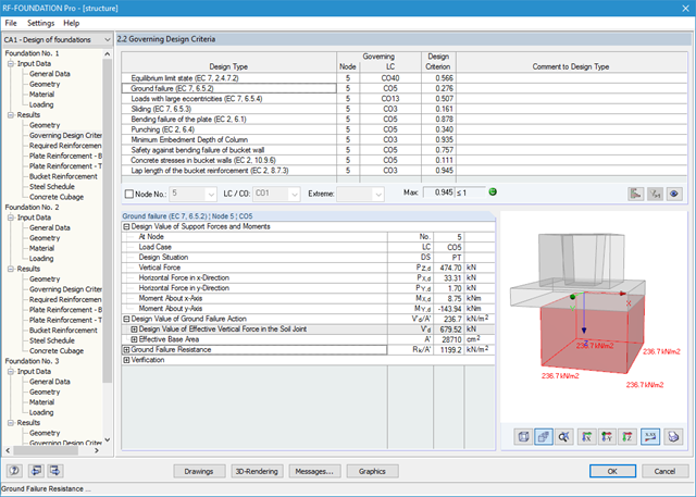
It is possible to perform the following designs:
- Equilibrium limit state design
- Uplift limit state design
- Ground failure (soil contact pressure) design
- Strong eccentric loads design
- Design of foundation torsion and limitation of gaping joint
- Sliding design
- Settlement calculation
- Bending failure design of the plate and bucket
- Punching shear design
Foundation and bucket dimensions can be user-defined or determined by the module. You can edit the determined reinforcement manually. In this case, the designs are updated automatically.