
In the https://www.dlubal.com/en-US/products/rfem-fea-software/add-ons-for-rfem-6/design/stress-strain-analysis stress-strain add-on, you can define a component-dependent limit stress cycle and consider it for the design.

In the RFEM add-on Surface Concrete Design allows you to perform the fire design according to the simplified table method (EN 1992-1-2, Chapter 5.4.2 and Table 5.8 and 5.9) for walls and ceilings made of reinforced concrete.

When generating shear walls and deep beams, you can assign not only surfaces and cells, but also members.

Get a better understanding of the stress distribution within member cross-sections using clipping planes.

In the Concrete Design add-on, you have the option to define an existing vertically oriented punching shear reinforcement. This is then taken into account in the punching shear design.

In RFEM, the oriented strand board (OSB) material is available for the USA and Canada. The material parameters are taken from the "Panel Design Specification manual".

The "Bracing in Cells" function allows you to generate diagonal bracing with just a few clicks. You can find this feature under Tools → Generate Model – Members → Bracing in Cells.

In RFEM and RSTAB, you can visualize the flow field quantities of pressure, velocity, turbulence kinetic energy, and turbulence dissipation rate for the wind simulation.
The clipping planes are aligned with the respective wind direction.

In the ultimate configuration of the steel joint design, you have the option to modify the limit plastic strain for welds.

The "Base Plate" component allows you to design base plate connections with cast-in anchors. In this case, plates, welds, anchorages, and steel-concrete interaction are analyzed.

In RFEM, you can generate surfaces from members with the library cross-sections as well as from the members with the RSECTION cross-section.

You can neglect openings with a certain area in the building model calculation. This function can be activated in the global settings of the building stories. A warning message appears saying that the openings have been neglected.

Are you looking for a formula relevant for your structural design? Just ask our AI chatbot Mia!
Mia shows you the right formula, with explanations, if necessary.
.png?mw=640&hash=9de889f94dda719e52d438f3fb6a495d2dce9a98)
Use the "Independent mesh preferred" option in the FE mesh settings to create an independent FE mesh for the integrated objects.
This allows you to generate a significantly more detailed and precise FE mesh for individual objects that are integrated into one another.
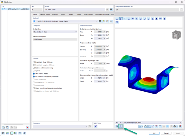
In the "Edit Section" dialog box, you can display the buckling shapes of the Finite Strip Method (FSM) as a 3D graphic.
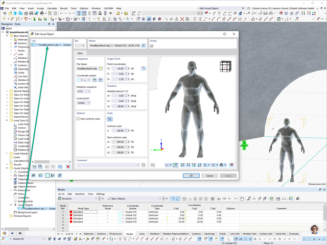
In RFEM 6 and RSTAB 9, you have the option to enter "Visual Objects" as guide objects. You can import the file formats 3ds, stl, and obj.
These objects allow you to create a better reference to the dimensions.

Do you have individual column sections and angled wall geometries, and need punching shear design for them?
No problem. In RFEM 6, you can perform punching shear design not only for rectangular and circular sections, but for any cross-section shape.

In the Construction Stages Analysis (CSA) add-on, you can use built-up cross-sections by means of what are known as phase sections. This allows you to activate and deactivate the parts of the "Parametric - Massive II" section type throughout the construction stages.

- Design of five types of seismic force-resisting systems (SFRS) includes Special Moment Frame (SMF), Intermediate Moment Frame (IMF), Ordinary Moment Frame (OMF), Ordinary Concentrically Braced Frame (OCBF), and Special Concentrically Braced Frame (SCBF)
- Ductility check of the width-to thickness ratios for webs and flanges
- Calculation of the required strength and stiffness for stability bracing of beams
- Calculation of the maximum spacing for stability bracing of beams
- Calculation of the required strength at hinge locations for stability bracing of beams
- Calculation of the column required strength with the option to neglect all bending moments, shear, and torsion for overstrength limit state
- Design check of column and brace slenderness ratios

The relevant input for the design is defined in the Seismic Configuration. Afterwards, a new Seismic Configuration can be defined by entering a descriptive configuration name, and then selecting the applicable SFRS frame type and member type.